
The MC3479P integrated circuit is housed in a 16-pin DlL enclosure and contains all the elements, including the power steps, to drive a two-phase stepper motor from digital TTL levels, such as those obtained at the output of a PC.
In Figure 1 we have the equivalent internal diagram of this integrated circuit.

As we have seen, this circuit has 4 sections or input blocks, a logic circuit for decoding and the power steps for the external circuit, and it can operate with voltages from 7.2 to 16.5 V.
The maximum current of each output is 350 mA and damping diodes are included to protect the internal circuits.
The circuit also has a select input which allows you to operate in half-step mode. The inputs are compatible with TTL CMOS logic.
In Figure 2 we have an application circuit for this step motor control by directly driving a motor.
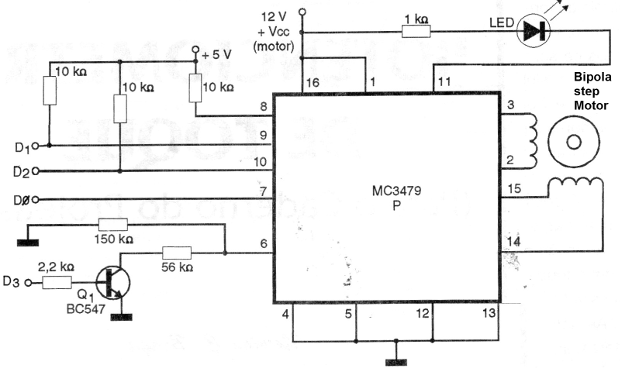
This circuit feeds a 12 V motor from TTL inputs of 5 V, as we can observe by the two voltages used in polarization and power.
Notes on the features:
The maximum output current drained by the circuit depends on the resistor connected between the pin 6 and the ground of the integrated circuit.
It is possible to use the pin 6 in two other functions: set the internal logic to a certain state (which is done by D3 in the circuit of Figure 2) and also reduce power consumption.
Revised 2017


