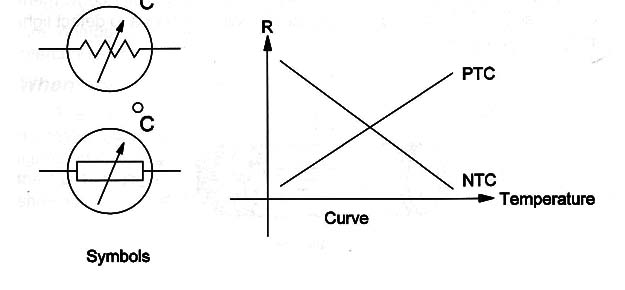
They are formed by materials (alloys and mixtures) that have special thermal properties suitable to the task.
Symbols, Types, and Characteristic Curve
Figure 1 shows the symbols used to represent these components, types, and the characteristic curve.

The size of the component determines how fast it is when altering its resistance during a temperature change.
This is an important factor in some applications and is referred to as readiness.
The format and size depend on the application.
Specifications
The NTCs and PTCs can both be specified by a manufacturer or part number and a nominal resistance, or a resistance in the ambient temperature (normally 20 degrees Celsius).
Also refer to Figure 1 for the characteristic curve, a graphic representation of the changes of resistance with the temperature.
Where they are found
The reader will find NTCs and PTCs in many electronic circuits used in electric installations or even in electronic appliances.
Some fire alarms and ambient temperature controllers used with air conditioners, as well as many other devices, use one of these components as a sensor.
They are installed in a place where the temperature can be detected.
The signal is then sent to a remote device that acts on the element to be controlled (air conditioner, alarm, fan, relay, etc).
Testing
The NTCs and PTCs can burn or break.
In this case, the resistance will increase and it can open the circuit.
The simplest test consists of taking the resistance measurement using a common multimeter.
Moisture can alter the nominal resistance of high-resistance NTC or PTC inducing a circuit into a wrong operation.
This is important to be considered if the NTC or PTC is used as a sensor and not protected from moisture or ambient action.


