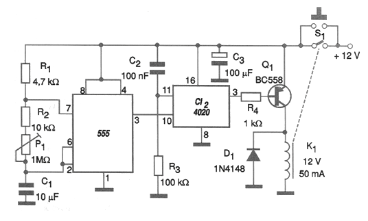
One of the problems with the 555 integrated circuit, normally used when timing is desired, is that in addition to 1 hour, the need for high value capacitors and resistors makes the circuit unstable. In fact, the maximum time of this order is due to the limitation of the capacitor to approximately 2 200 uF and the resistor to around 1.5 M ohms. One way to obtain long timings, exceeding 15 hours, as in the case of the circuit shown in the figure, is with the use of a 14-stage CMOS binary counter, such as the 4020 integrated circuit. Thus, the pulses generated by the 555 are counted up to 16 384 before the relay is activated, thus ending the timing. It is easy to see if the 555 generates 1 pulse every 10 seconds, we will get a 160 840 second timer! In the presented circuit, the timing starts when the S1 button is pressed, in which case the relay closes the contacts and the 555 starts to oscillate. At the end of the count, the relay opens the contacts, automatically disconnecting the circuit. The timing adjustment is made in P1. To obtain an adjustment accuracy, an LED in series with a 1 k ohm resistor can be connected to pin 3 of the 555, then adjusting the pulse frequency. The flashing interval multiplied by 16 384 will give the adjusted timing. The circuit can work with 6 V relays and the value of C1 can be changed for different timing ranges. We observed that during the time interval the relay remains energized, being basically the current in its coil that will determine the consumption of the device. The resistor and capacitor on the reset pin 11 ensure that the 4020 count starts from zero.