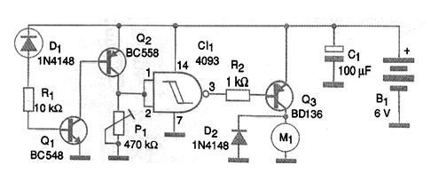
Another way to increase the sensitivity of the circuit with the amplification of the sensor current is through the configuration with complementary transistors shown in the figure. When Q1 drives, by reducing the resistance of the sensor (increasing the temperature), transistor Q2 also drives and thus the logic level at the door input rises. With switching the output goes to low level saturating transistor Q3. With Q3 driving, the engine is started, providing the desired ventilation. The circuit can be supplied with voltages from 5 to 12 V depending on the voltage of the motor used. The Q3 transistor must have a heat radiator and higher current equivalents can be used. Power Darlingtons and even 12 V power MOSFETs can also be used.