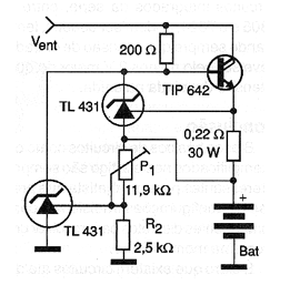
In the figure we have a battery charging circuit for currents up to about 5 A. In series with the battery, an ammeter and a voltmeter can be connected in parallel so that the charging process is monitored. The 0.22 resistor is highly dissipating and the trimpot P1 adjusts the charging voltage, that is, the voltage at which the battery is considered charged. Two Texas Instruments TL431 voltage references that suggest this circuit are used. The Darlington transistor supports equivalents and must be mounted on an excellent heat radiator.