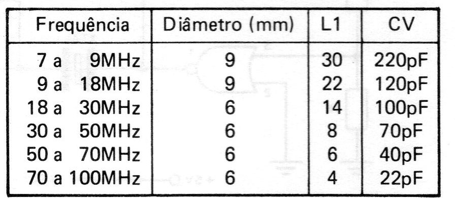
The RF oscillator in the figure provides signals in the range of 7 to 100 MHz, using an overtone crystal and can be supplied with voltages between 9 and 18 V. The difference in relation to the previous circuit (CIR8795) is in the mode according to the signal is withdrawn. We have an RF transformer formed by L1 and L2. The characteristics of these two coils depend on the frequency, according to the following table:
Coil L2 consists of 2 to 4 turns of wire over L1. The smallest number of turns is used at the upper end of the range. The performance of the circuit depends on the gain of the transistor. Recommended types are BF494, BF495, 2N2218 or 2N2222. The 1k8 base polarization resistor can be changed depending on the supply voltage, so that the current consumption does not exceed 20 mA. Smaller values are used with higher voltages, up to the minimum around 1 k. Remember that, in this type of circuit, the CV capacitor and the L1 coil form a “tank” circuit that does not determine the frequency of operation, but rather the performance in the signal transfer to the external circuit. If an adjustment for greater efficiency is not achieved, the coil must be changed. Another important characteristic of this circuit is that it allows the production of signals of multiple frequencies of the crystal (operation in harmonics). If we have a 6 MHz crystal and we adjust the resonant circuit to 24 MHz, we will produce this frequency, without problems. The adjustment of the operating point must be done with the help of a grid-dip or frequency meter.