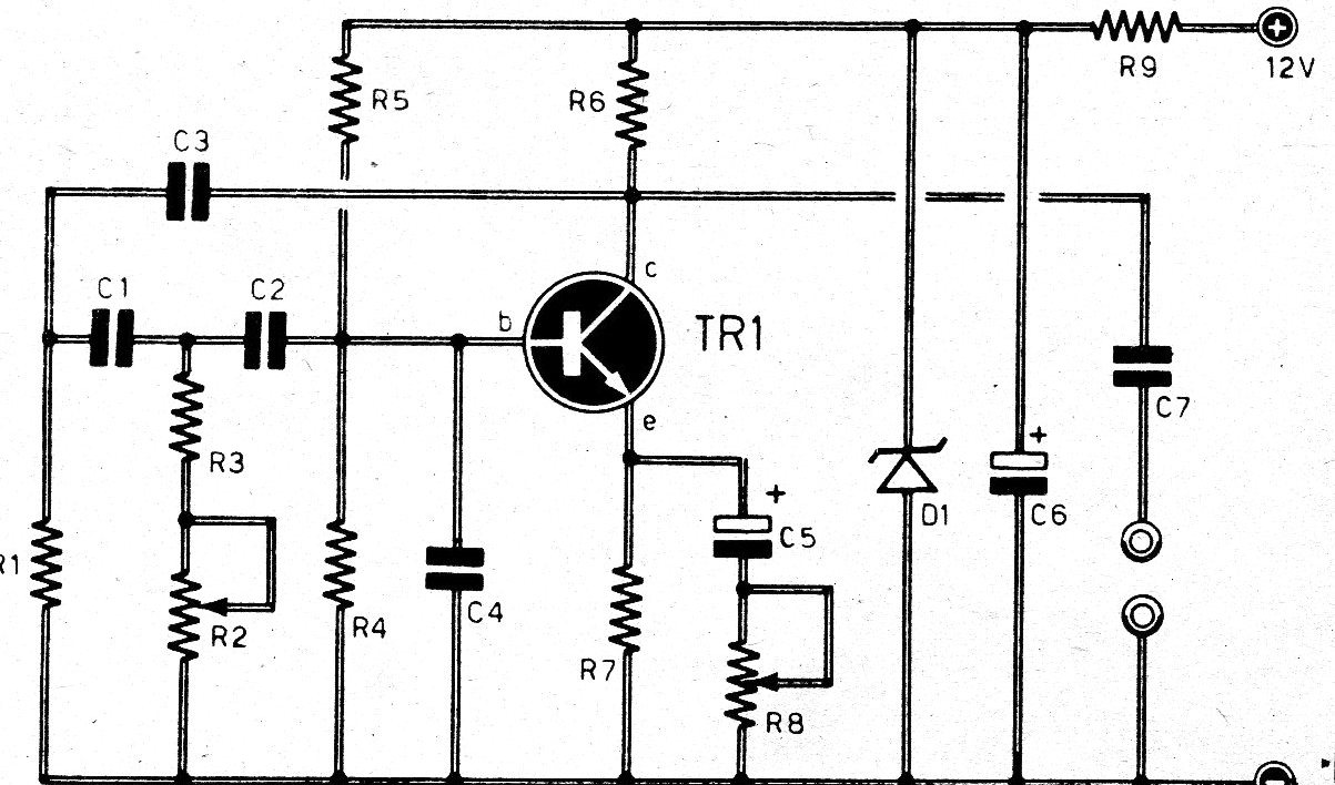
This article was written by A. Fanzeres in the 1970s. We kept the original text. With the circuit we present, it is possible to obtain an audio signal, whose frequency is variable (via R2) and the amplitude (via R8), at the output terminals. The circuit is simple and does not present any difficulty in operation. The output power or amplitude can be applied to an amplifier if an extra strong signal is desired, but for common measures and applications the signal is already adequate.
LIST OF MATERIALS
R1 - 1,800 ohms
R2 - 2,500 pre-set type
R3 - 680 ohms
R3 = 680
R4 .- 2,200
R5 .- 10,000
R6 - 1,000
R7 - 220
R8 - 100 pre-set type
R9 - 680
C1 - 4,700 pF
C2 - 4,700 pF
C3 - 4,700 pF
C4 = 47 pF
C5 = 100 uF x 25 v., Electrolytic
C6 = 10 uF x 25 volts, electrolytic
C7 - 47,000 pF
TR1 - BC 208 (BC548)
D1 - Zener BZX 79 (C8V2), 8.2 volts