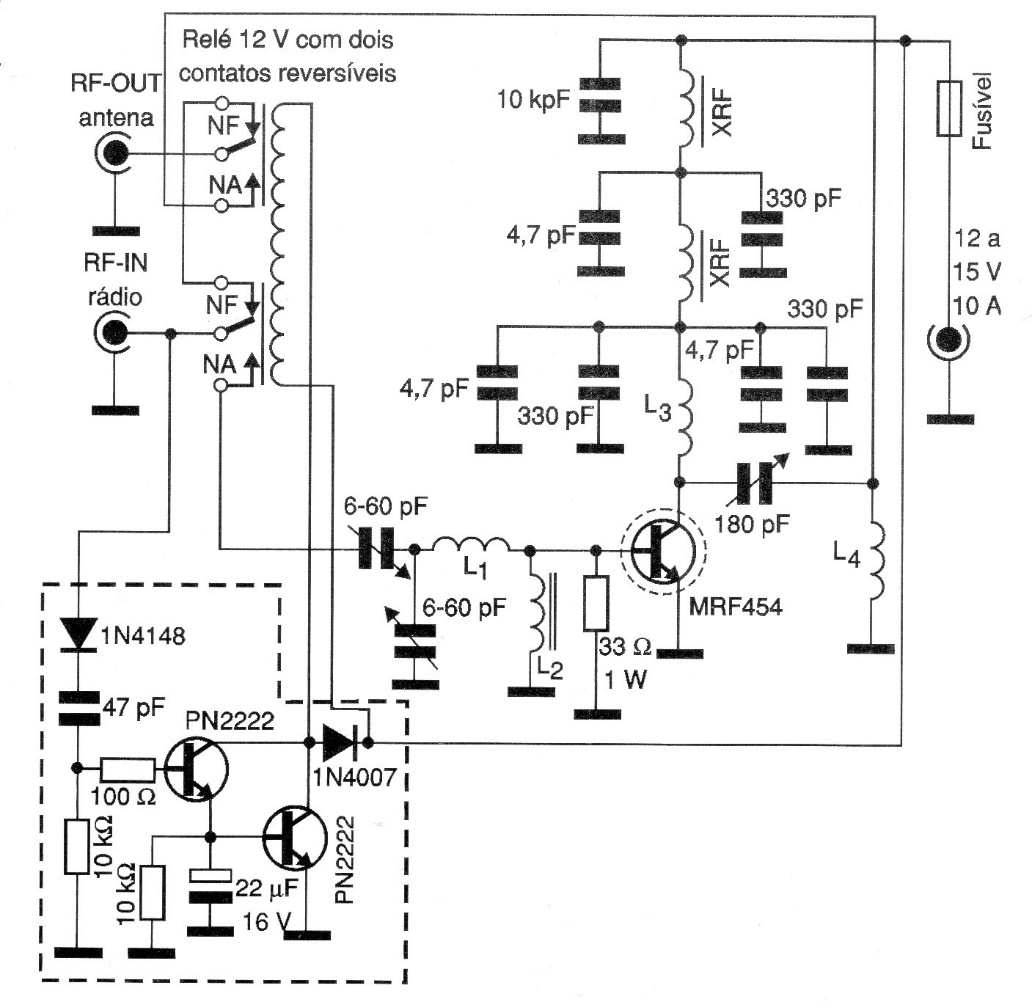
Although the so-called “boots” or amplifiers that increase the power of transmitters are not allowed in certain bands, as in the case of the PX, the circuit shown serves as an illustration, and the reader should be responsible for its possible misuse. The input power must be of the order of 5 W and the MRF454 transistor must be mounted in an excellent heat sink. All connections between components must be short and the assembly of the coils requires great care. These coils have the following characteristics:
L1 - 3 turns of 18 AWG wire with 1 cm internal diameter and 1 cm long.
L2 - 17 turns of enameled wire of such thickness that, using a ballpoint pen, results in a 1.3 cm long coil.
L3 - 10 turns of wire 20 or 22 AWG with 8 mm internal diameter
L4 - 4 turns of enameled wire 20 AWG in ferrite rod 1 cm in diameter with 2 cm in length
The XRF shocks are formed by 4 turns of enameled wire 20 AWG on ferrite of 1 cm of internal diameter for 2 cm of length. The power supply must supply at least 10 A of current.