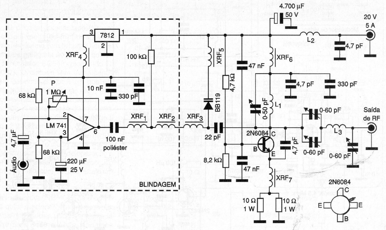
The range, of course, also depends on the antenna and local geographic conditions, remembering that there are legal restrictions on the use of this type of equipment. The connections between the components must be as short as possible and the plate must be made of fiberglass. The RF shocks have the following characteristics: XRF1, XRF2, XRF3 and XRF5 consist of 150 turns of enameled wire 32 in the form of ferrite 1 cm in diameter with 2 cm in length. XRF4, XRF6 and XRF7 consist of 6 turns of wire 22 in ferrite of 1m in diameter with 2 cm in length. The coils have the following characteristics:
L1 consists of 2 turns of AWG 18 with 1 cm in diameter
L2 - 100 turns of AWG wire 32 on a matchstick
L3 - 4 coils of AWG wire 16 in the form of 1 cm in diameter
A good performance dipole or ground plane sized for the transmitter frequency can be used as the antenna. Note that the modulating step with integrated circuit 741 must be provided with shielding so that no humming occurs. The capacitors are of good quality ceramic and the resistors must have the minimum dissipations indicated in the diagram. The power transistor must have a heat radiator as well as the voltage regulator integrated circuit.