
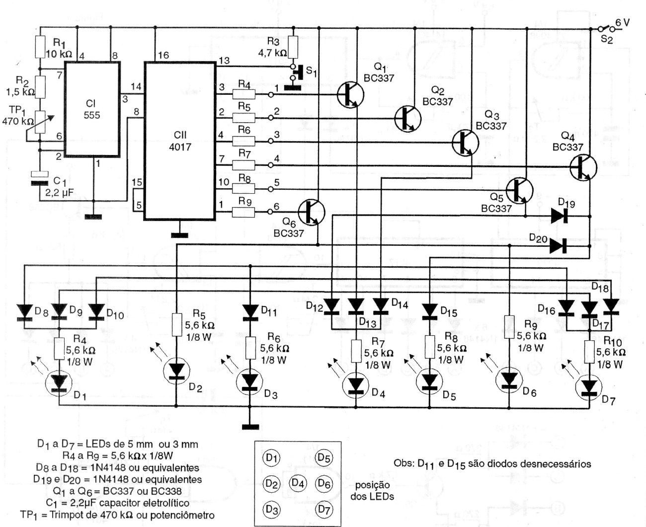
This circuit is from 1997 documentation, based on the well-known integrated circuit 555 and 4017. The circuit has LED indicators that emulate the face of a game die. The circuit is powered by 4 common batteries and the speed adjustment of the data flow is done in TP1. The Q2 emitter is connected to the D8 anode and other diodes in this line.
| Clique na imagem para ampliar |


