
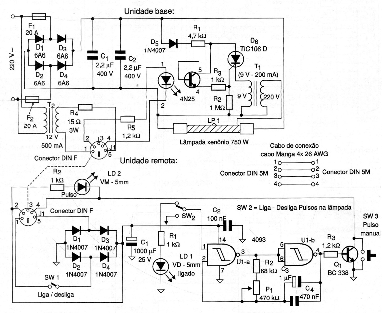
We found this circuit in a 2006 documentation. The circuit has two parts: a base where we have the high voltage sector and a remote unit where we have the adjustable oscillator that determines the rhythm of the lamp's flashes. What you do is basically rectify and then filter the alternating current from the grid, charging two capacitors C1 and C2. At this point we have a continuous voltage of approximately 325 V. When the base unit receives a pulse from the remote unit, T1 generates a high voltage pulse at the lamp control terminal by firing it. With that, C1 and C2 discharge, being immediately loaded into a new flash.
| Clique na imagem para ampliar |


