
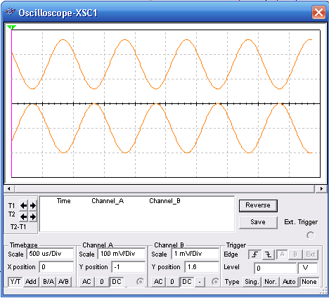
The gain of the Operational Amplifier in the figure is given by the ratio between R1 and R2. In this cases the gain is 100, but you can change the component to other gains. The circuit uses a simgle power suply with voltages between 9 and 15 V. Other operational amplifiers can be used. Observe the adjustments for the function generator (10 mV) and for the oscilloscope. The upper frequency limit for the circuit is about 100 kHz.
The input impedance is about 10 k Ω. The waveshape of the signals displayed by the virtual oscilloscope of the MultiSIM Blue is shown bellow.
To download the simulation files and Netlist - click here (msb0018e.zip)


