

Oxygen (O2) is an oxidizing gas, ie it is the reaction that occurs between this gas and other materials that causes what we call combustion or burning. There is no combustion in the absence of oxygen. and a change in their concentration in an environment may indicate gas leaks.
How to detect variations in oxygen concentration in an environment is a problem whose solution can lead to several electronic equipment of great utility.
For example, gas leak detectors for domestic use which are based on the change in oxygen concentration due to the presence of the combustible gas. We can cite the so-called "lambda probes" used in the car engine outputs, which verify that all fuel has been burned and whether it is necessary to increase or decrease the presence of this gas in the mixture.
On an industrial scale these devices can be used to detect the presence of oxygen in environments in which it can not be present. There are several types of oxygen sensors involving chemical techniques such as galvanic cells and semiconductor devices.
The most common type is Zirconium Oxide, which is what we will analyze in this article.
ZIRCONIUM SENSORS
In figure 1 we have a section view of a ceramic zirconium sensor (zirconium oxide) from which we analyze its principle of operation.
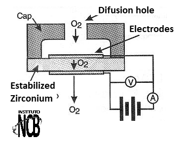
Between two porous electrodes (to give passage to the ambient air) there is a disc of zirconium oxide. This material has semiconductor properties where the charge carriers that establish the current are ions of oxygen.
Thus, if we establish a voltage between the electrodes, the current that will circulate depends precisely on the concentration of oxygen ions in the material.
This current is extremely low, on the order of 5 ?A, requiring appropriate amplifier circuits. The semiconductor properties of zirconium, however, only manifest at a very high temperature, of the order of 400 degrees Celsius.
In the case of oxygen sensors used in cars, as the gas is already heated from the engine, the sensor can be placed directly in the way indicated. However, in the case of a measure of the oxygen concentration of ambient air or a place where it is at low temperature, the sensor needs to be heated.
This is normally done by an additional element that is found on these sensors and which serves as heating element. The heating element is a platinum wire that is driven by a somewhat intense current that heats it up to the operating temperature of the sensor.
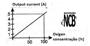
In figure 2 we see an operation curve of this type of sensor showing how the current depends on the oxygen concentration.
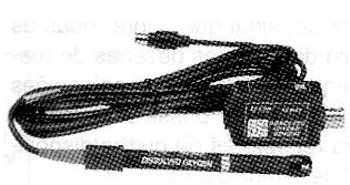
Common commercial types such as Fujikura, Pasco, Electrovac and others (whose pages with information can be accessed over the Internet) can detect oxygen concentrations in the range of 0 to 98% with good accuracy, reaching 1000 ppm according to type.
In figure 3 we have a photo of a commercial oxygen sensor from the companies mentioned above.
TYPICAL CIRCUITS
A typical oxygen sensor circuit for ambient use (room temperature gas) has the block configuration shown in figure 4.
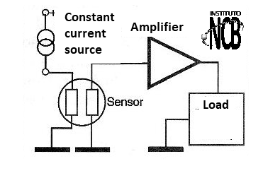
A heating circuit keeps the temperature of the sensor at approximately 400 degrees Celsius so it can run. The ideal for applications where more precision is required is to use a constant current source in this circuit. In less critical applications, such as simple leakage or oxygen presence alarms, a common source can be used.
The electrodes are polarized by a low voltage appearing on an external circuit a current (or a voltage) proportional to the concentration of oxygen. An amplifier stage, usually using an operational amplifier is set to increase the signal from the sensor output.
This signal can then be applied to a numerical indicator or to a relay or to a circuit that triggers a warning system. The warning circuit can be set so that the trip occurs with certain gas concentration.
PRACTICAL CIRCUIT
In figure 5 we have a very simple gas alarm circuit, which uses the TGS308 sensor.
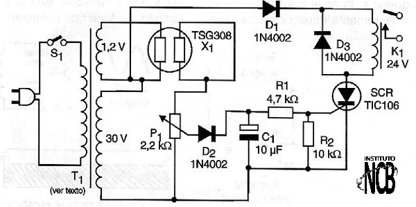
The circuit operates a 24 V relay when the oxygen concentration exceeds a certain value. Other equivalent sensors can be used in this same configuration and only the reader should check the heating voltage.

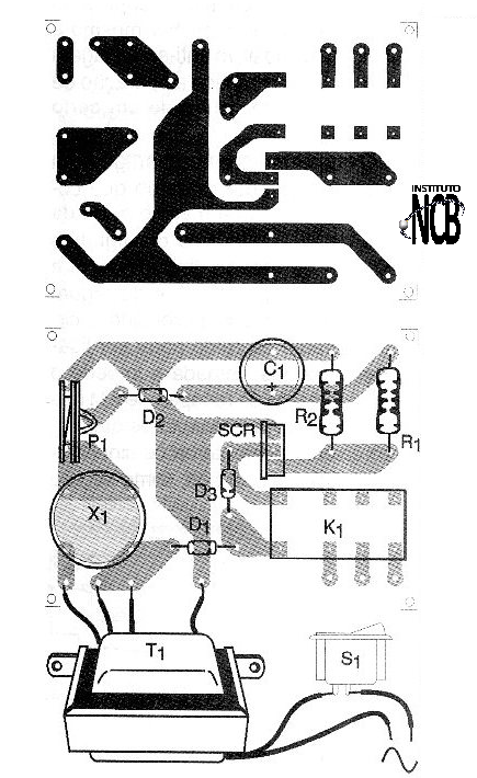
In figure 6 we have a printed circuit board suggestion for this alarm.
The SCR does not need to be mounted on a heat radiator and the transformer secondary current is 50 mA for the 30 V winding, and 500 mA for the 1.2 V winding. We note that this circuit, because it is simple, has no activation delay and can fire when it is turned on. If this occurs, a capacitor of 470 ?F should be connected after the diode in series with the relay, and a 100 ohm resistor associated in series with the diode.
Semiconductors:
SCR - TIC106 or MCR106 - silicon controlled diode
D1, D2 and D3-1N4002 - Rectifier diodes
Resistors: (1/8 W, 5%)
R1 - 4.7 k ohm
R2 - 10 k ohm
P1 - 2.2 k ohm - trimpot
Capacitors:
C1 - 10 ?F / 30 V - electrolytic
K1 - 24 V relay
X1 - TGS38 sensor or equivalent
T1 - Transformer with primary according to the local and secondary network of 1.2 V x 500 mA and 30 V x 50 mA.


