TRIAC Structure
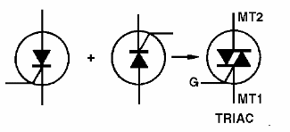
TRIAC, another member of the thyristor family, can be considered as a component obtained by connecting two opposing Silicon Controlled Rectifiers, SCRs, having in common a gate, as shown in Figure 1.
Of course, in the manufacturing process, the two devices are obtained from a single silicon wafer, as shown in Figure 2.
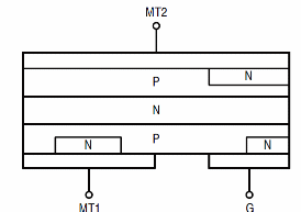
Each of the “SCRs”, that a TRIAC is made, already has its known funcion, so we can imagine this component as something like a “bilateral key” which drives a two-way current, and can be discharged by a signal applied to its gate element.
Note that TRIAC has two main terminals: MT1 and MT2 and a gate terminal.
The characteristic curve of the TRIAC is shown in Figure 3. Note that it is equivalent to two opposing SCRs with the characteristic of the first "folded" quadrant to the third.
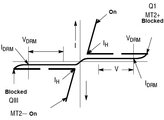
The meaning of the several voltages and currents which appear in this chart will be explained in the item “specifications”.
A TRIAC is used in alternate current, AC, circuits only connected in series to the load, as shown in Figure 4.
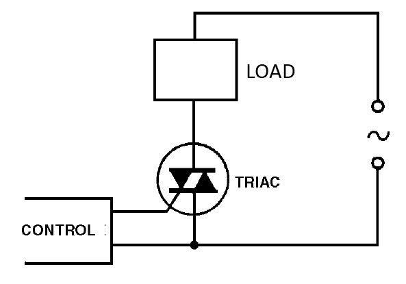
For discharging it, we must apply a positive or negative voltage to its gate, which allows it to be triggered in the AC circuits in any of the semi-cycles.
The discharge voltage for this component is 2 V, and typical currents in the range of 10 mA to 200 mA are found, depending on the power of the component. TRIACs can be triggered in 4 different ways, which should be observed in their applications:
I + mode: In this mode, the MT2 terminal will be positive compared with the MT1, and the gate current has such a way that it enters the component, i.e., positive gate.
I - mode: In this mode, the MT2 terminal will be positive compared with the MT1, and the gate current leaves the component, that is, we have a negatively polarized gate.
III + mode: In this mode, the MT2 terminal will be negative compared with the MT1, and the positive gate, i.e., with the current entering the component.
III - mode: In this mode, we have the MT2 terminal negative compared with the MT1, and apply a negative pulse to the trigger terminal.
In Figure 5, we have the triggering modes of a TRIAC.
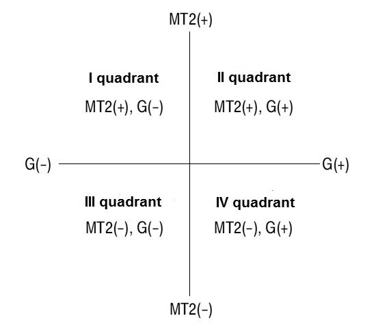
In modalities I + and III-, we obtain greater sensitivity to the triggering for a TRIAC than in other modalities.
Housing
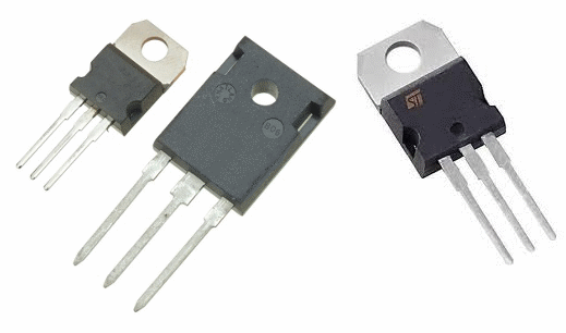
TRIACs are obtained in the same housings as SCRs, power transistors and Metal-Oxide Semiconductor Field-Effect Transistors, MOSFETs. In some cases it's hard to know if it's really a TRIAC just by looking at the codes.
Texas Instruments, for example, has a number of SCRs and TRIACs which are named “TIP” and all have the same enclosures. The ideal is to consult the datasheet.
In Figure 6, we have common housings for TRIACs.
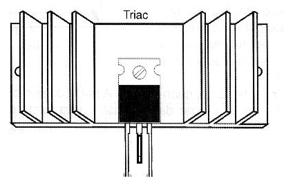
Because these devices are used in power controls which operate at high currents, they are all equipped with heatsinks to assemble.
TRIAC Specifications
As with SCRs, we need to know the main specifications of TRIACs in order to use them properly.
The limits must be observed so that the component will not burn.
The main specifications we must observe for TRIACs are:
- Maximum Working Voltage (VDRM)
This feature refers to the maximum voltage that can appear between the terminals of a TRIAC when it is off. For common types, it can range from 50 or 100 V to over 1000 V.
We can also specify this voltage in terms of peak for short pulses, so that in the manuals the conditions appear under which the value is valid.
In most cases, however, the value refers to the peak of a sinusoidal voltage, since the main application of the component is precisely in circuits connected to the local network.
- IT Maximum Current (RMS)
Note that the indicated value already specifies that it is an rms current, that is, the effective value of the AC, since the component will normally operate in AC circuits.
- IGT Trigger Current
Here we have the indication of the sensitivity of the behavior towards the trigger, this current being specified in milliamps.
It is also important to know the maximum current intensity that we can apply to the TRIAC gate without danger of damaging it, as in many applications special devices are used for this purpose.


