
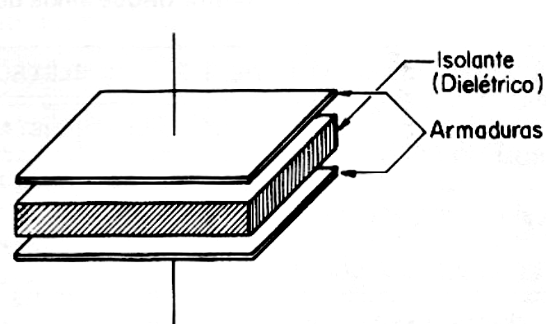
Two armatures (conductors) separated by an insulating medium form a capacitor (Figure 1). The type of material used as the insulator gives the name to the capacitor, so we can have capacitors of mica, paper, polyester, ceramic when these are the materials used as insulators.
In the practice of electronics, the technician will find several types of capacitors with formats and capacitances in a wide range of values. For each application, we have recommended types in view of the properties of both the materials used as insulators, called dielectrics, as well as the construction itself.
Even with different characteristics in electronic circuits, the purpose of a capacitor is always the same: to store electrical charges.
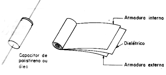
How a capacitor does this is what we will see next. A tubular capacitor, that is, made with the armatures wrapped, as shown in Figure 2, in order to obtain greater capacitance in a reduced volume, is not suitable for applications involving high frequency signals. This is because, winding the material which forms the armatures, usually aluminum strips, we form a coil that starts to manifest a certain inductance. If the frequency is high, this inductance predominates over the capacitance, and the component that should be a simple capacitor actually behaves as a mix of capacitor and inductor.
Metallized polyester capacitors, even if flat in construction, are also not suitable for high frequency applications (RF circuits), since the insulating material does not have proper properties for this purpose.
Ceramic plate, disk or even tubular capacitors already have a series of characteristics which allow their use without problems in high frequency circuits.
Energy Storage
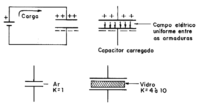
If we connect a generator to the two armatures of a capacitor, as shown in Figure 3, a certain number of charges will flow and remain in the armatures in question, loading the capacitor.
The number of positive charges in one armature will be exactly the same number of negative charges in the other armature.
If we turn off the generator, these charges will be kept in the armature by the forces of electrostatic attraction that manifest. The intensity of these forces depends not only on the separation of the reinforcements, but also on the nature of the material which exists between them, that is, the dielectric.
There are materials in which the lines of force can act in a stronger way, polarizing their molecules and, with this, the intensity of the field will be stronger. If we use a material of this type in a capacitor, we can multiply the number of charges stored. (Figure 3).
By placing a sheet of glass between the armature of a capacitor, we can increase its capacitance by 4 to 10 times, that is, the amount of load it can store.
Each material has a "dielectric constant" which precisely tells how it can be used to multiply the capacitance of a capacitor in relation to the vacuum whose constant is 1.
Below is a table of dielectric constants for common materials:
Bakelite - 4
Bitumen - 93
Celluloid - 3.5
Ebonite - 4
Glass - 4 to 10
Mica - 4.5 to 8
Paraffin - 2.2
Porcelain - 6.5
Polystyrene - 2.5
Rubber-2.6
The important thing is that, in this electric field which retains the charges in the armatures, a certain amount of energy is stored.
We can compare this field to a contracted spring which retains potential energy and can be used to power an external circuit.
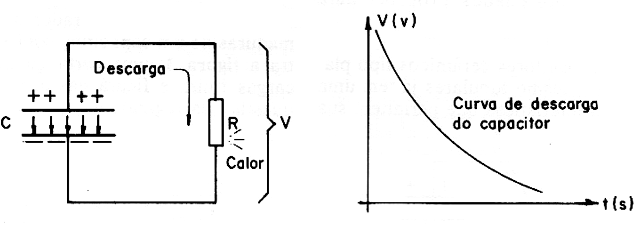
In fact, when we connect a charged capacitor to an external circuit, a resistor, for example, as shown in Figure 4, the charges flow with the gradual decrease of the field lines (which weakens). The current then produces heat which is the energy stored in the capacitor that dissipates.
We can calculate exactly the amounts of energy involved in this process in a relatively simple way:
The capacitance (C) of a capacitor can be defined as the load (Q) / voltage (V) ratio, which must be constant.
If a capacitor stores a charge of 1 coulomb under voltage of 1 volt, we say that it has a capacitance of 1 farad.
C = Q / V (1)
In practice, we work with capacitances much less than 1 Farad, we prefer to use submultiples such as microfarads (millionth part of 1 farad abbreviated by µF), nanofarad (billionth part of 1 farad, abbreviated by nF) and picofarad (trillionth part of 1 farad, abbreviated by pF).
The graph in Figure 5 shows that the Q / V ratio remains constant in the charge of a capacitor. Thus, if we make a graph representing the increase in the number of charges in a capacitor's armatures as a function of the voltage that "pumps" them, we will see that it corresponds to a line.
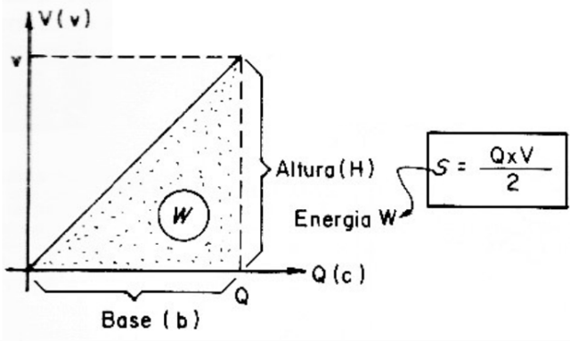
The area on this line represents the amount of energy that we have to spend to “pump” the charges to the armatures and, therefore, the “W” energy that the capacitor stores.
As the figure we have, which corresponds to the energy is a triangle, its area can be calculated by the formula:
S (B x H) / 2
Where S is the area; B is the base and H is the height.
In our case, the base is Q, that is, the amount of stored loads; Vis, the voltage applied in volts.
Our formula will then look like:
w (Q x V) / 2
In short, to calculate the stored energy (in joules —J) we multiply the charge by the voltage and divide the value found by 2.
In practice, it would be better to work with the capacitance and not with the charge, as this is a value that is normally not available to us immediately in a capacitor.
Since the C = Q / V ratio is constant, we can use it to substitute in formula (2).
w = (C x V x V) / 2
or
w = (C x V2) / 2
Thus: Q = C x V
Replacing in (2)
Without a doubt, this formula is much better to calculate in practice how much energy a capacitor stores Take an example:
Calculation Example
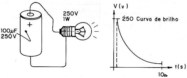
Let's suppose that we want to calculate the energy stored in a 100 µF capacitor when we subject it to a voltage of 250V.
In this case:
C = 100 µF = 100 x 10-6 F
V = 250 V
Applying formula (3):
w = (100 x 10-6 x 250 x 250) / 2
w = 6.25 Joules.
If the reader takes into account that 1 joule per second corresponds to 1 watt, the "huge" charge stored in this capacitor will light a 1 watt lamp for just 6.25 seconds! Without a doubt, capacitors actually store energy, but an amount that does not allow us to use them as large-scale energy sources! Capacitors store only small amounts of energy, but with great benefit for electronic circuits. (Figure 6).
Conclusions
Note that, in the formula, the voltage appears with exponent 2 while the capacitance does not. This means we can obtain more energy at higher voltages and not at higher capacitances. Thus, we get much more stored energy from a 10 µF capacitor charged with 100 volts than from a 100 µF capacitor charged with 10 volts!
It is clear that the maximum voltage we can apply to a capacitor has a limit, given by the characteristics of the dielectric.
We conclude then that, even if in practice the capacitor is not a device suitable to function as a large-scale reservoir of "electricity", in electronics, where short-lived transient phenomena need to be worked on, the small energies involved may well be within what relatively small capacitors can handle, hence its wide range of practical applications.


