It is the inertial sensors that determine the position of your phone by changing the screen's appearance when you rotate it. It is the inertial sensors that keep parallel two-wheeled vehicles balanced. It is the inertial sensors that keep drones balanced as they travel through the air. It is the inertial sensors that control a robot balanced when it is stopped or moving.
These are just some of the possible applications for these sensors that can be found in integrated circuits, ready to be used in any project type.
Inertia
To understand how inertial sensors work, we must return to the school benches and remember inertia from our high school physics classes. We can say that inertia is the property that all physical objects must react to any change of state that occurs. As a change of state, we understand the modification of its movement. Thus, when we try to take a certain mass out of rest, it reacts, due to its inertia, producing a force opposite to that which tends to move it. If we neglect friction, this reaction force will depend on the mass of the object.
Likewise, an object in uniform motion tends to react to any change in its condition, due precisely to this property we call inertia. To break and accelerate the object, we need to apply a force to overcome the inertia, which is precisely the force with which it reacts. Similarly, we need to use a force to change its trajectory, causing it to turn, for example. The force that must be applied depends precisely on the mass and speed of the object and the correction we want for its trajectory.
In other words, we need to apply forces if we want to change the movement state of a physical object that is of a certain mass. But inertia also manifests itself in other ways, used in some sensors that we will study. A disk spinning at high speed or a certain mass that spins tied by a string has a "moment of inertia". While in movement, the forces that appear are internal and are counterbalanced by the cohesive forces that keep the object in its shape. If these forces are overcome by excessive speed, the disk disintegrates.
However, if there is an external attempt to modify the movement, the disk reacts with greater force, the greater its mass and speed.
For example, if the disk moves parallel to the plane in which it rotates or even perpendicular to the plane, there are no forces that react to this. However, if we try to change the inclination of the plane of rotation, then things change. The disk reacts strongly to maintain its original position. That's why a top toy spinning at high-speed stays balanced. A vibrating blade can show similar behaviour. It also has a moment of inertia that depends on its mass and speed of vibration. Any attempt to change the plane of vibration causes it to react strongly with a proportional force.
The spinning disk and the vibrating blade are used in inertial sensors that we will study next. An inertial sensor is a sensor that is used to detect changes in position or movement conditions, working based on the principles we have studied.
Types of sensors
a) As for the signal obtained
Analogue - We can have inertial sensors that provide in their output an analogue signal, for example, a voltage, whose value depends on the inertial state modification condition they detect. These sensors can be used in simpler applications that do not require information processing, for example, using microcontrollers.
Digital - These are sensors that provide information regarding the magnitude detected and measured in digital format, being able to interface directly with a microcontroller. For example, they are sensors with I2C interfaces whose signals represent the magnitude measured in digital format.
b) Types
- Gyroscope
We started with this because it is the oldest and easier to build in larger sensors and other applications. A gyroscope is a device that consists of a disk that rotates at high speed and is mounted on a cardan system.
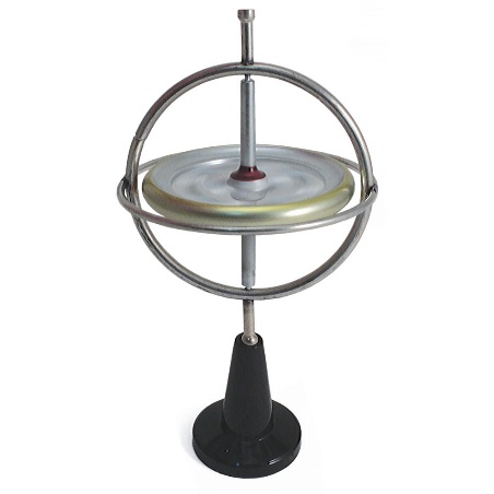
A change of the gimbal's position causes a force to appear that keeps the disc in its original plane of rotation. In a sensor, we can use means to detect when this change occurs and thus provide a signal to an external circuit. A variation of the disk gyroscope is the vibrating blade in which quartz blades usually are used, generating voltages when changes in the plane of vibration occur.
- Accelerometer
Another way to measure accelerations is through accelerometers. For this, there are several technologies.
a) Capacitive
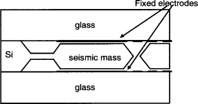
In this type of sensor, we have two metal plates or electrodes forming a capacitor. However, they have a gap that varies according to the acceleration to which the sensor is submitted. As a result, the capacitance of the sensor changes according to acceleration, thus providing a signal that can be measured.
The mobile plate is coupled to an inertial mass, a body with a certain freedom of movement to react to accelerations to produce the appropriate response. Capacitive accelerometers are indicated to monitor larger structures, given their characteristics. In Figure 2, we have the basic construction of such a sensor.
b) Piezoelectric
In this type of sensor, we have a piezoelectric material mounted on an inertial mass. Accelerating the sensor causes a proportional voltage to be generated. The force that appears on an inertial mass act on the piezoelectric material, deforming it and thus generating a voltage. In Figure 3, we have a simplified diagram of the construction of a piezoelectric inertial sensor.
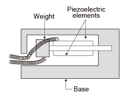
The sensitivity will depend on several factors, such as the type of piezoelectric material used, usually ceramic, the mass, and how the elements are assembled.
c) Piezo Resistive
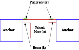
This type of sensor takes advantage of changes in the resistivity of materials subjected to mechanical stress. Likewise, what is done is to couple one or more wires of this material to a seismic mass that produces a force when subjected to an acceleration. This type of sensor is characterized by operating in a wide range of frequencies, including close to zero, and measuring short duration forces, such as shocks or knocks. As they are temperature sensitive, they need compensation circuits. In Figure 4, we have how a sensor of this type is built.
d) Hall Effect
The hall effect, used in magnetic field sensors, can also measure accelerations by simply having a special arrangement of elements that produce magnetic fields. Thus, in the case of inertial sensors, what is done is to couple a mass to a magnet and position this system so that the hall sensor is under the action of the magnetic field of the magnet, as shown in Figure 5.
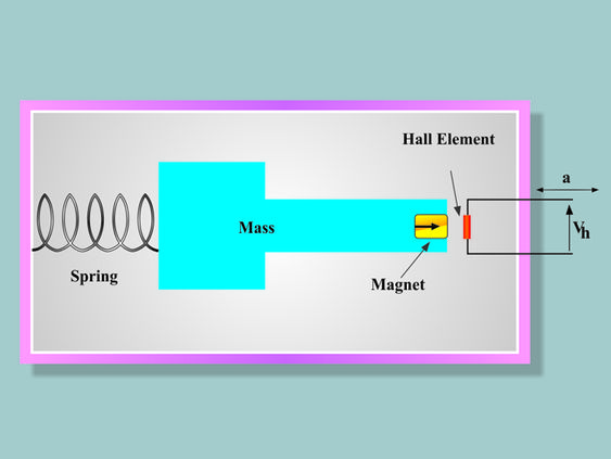
A spring allows the inertial mass to move, reacting to the acceleration of the assembly. As a result, the field acting on the hall sensor varies, providing a signal to the external circuit. Note that this type of sensor's response speed depends on the assembly of the mechanical elements.
e) Magnetic Resistive Accelerometers
Magnetic resistive materials change resistance in the presence of magnetic fields. Note that this is different from the case of the hall effect and sensors that change resistance under the action of mechanical forces.
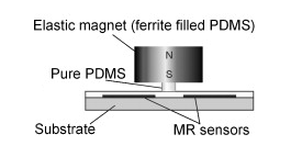
In this case, what is done is to attach a magnet to an inertial mass and place it in the vicinity of resistive magnetic material. Thus, the reaction of the inertial mass to an acceleration causes it to move and with it the magnet that produces the field. The movement causes this field to change the resistance of the sensing element. Refer to Figure 6.
f) Heat Transfer Accelerometers
It is an exciting technology that finds applications in specific cases. In it, an inertial mass is heated and a temperature sensor monitors its position.
g) Others
Other Techniques
Several other technologies can be found both in sensors in the form of integrated devices and parts arrangements. Thus, we can have the case of sensors in which an inertial mass penetrates a coil, changing the reluctance of the circuit with its movement, which depends on the acceleration. We can have optical systems in which an inertial mass alters the passage or reflection of a light beam, thus producing a corresponding output signal. Another possibility is to couple an inertial mass to a potentiometer through a mechanical system, thus obtaining resistance variations.
Characteristics
a) Orientation
Inertial sensors detect vector quantities forces and displacements; they have direction, orientation, and magnitude.
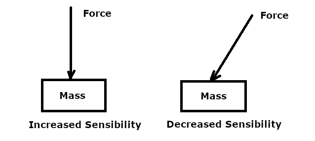
Thus their action requires them to be guided. The force that will act on the sensor, resulting from an impact, a change in speed or displacement, has an orientation, and this must be considered when positioning the sensor. Thus, as shown in Figure 7, the sensor must be positioned so that the action takes place in an orientation where maximum sensitivity is obtained.
If you want to have a response in any direction in which the force acts, the solution consists of mounting three sensors at right angles, as shown in Figure 8.
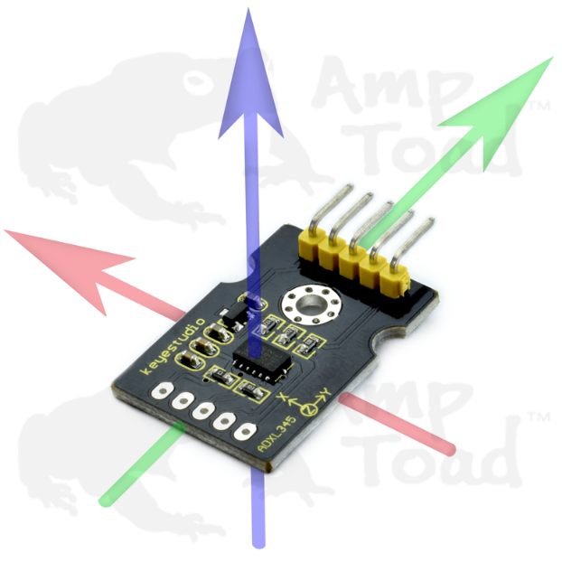
In this case, each sensor detects the force component according to its positioning, providing the external circuit with a corresponding signal. The external circuit makes the vector sum of the signals, thus providing the acceleration value (modulus) and the orientation (vector).
b) Readiness Or Response
Inertial sensors do not respond immediately to a force variation that occurs when they move. They need a certain time to respond. The various technologies we've seen offer different response times. This is the case with a temperature sensor. It needs to "accommodate" the temperature of the body or the environment in which it will measure, which takes time. The inertial masses or mode used will determine how long the sensor takes to react and, thus, its readiness. In a system where quick reactions are required, readiness is critical.
MEMs technologies (Micro-Electro-Mechanical) allow the development of tiny sensors that lead to speedy responses.
c) Sensitivity
Evidently, as an essential characteristic of the sensors, we have the sensitivity of their resolving capacity in detecting a change in position or speed.
Available Types
Today we have in the market a multitude of inertial sensors manufactured with technologies that provide them with characteristics of readiness, sensitivity and orientation that allow their use in virtually any project. They can be used in various projects with analogue outputs or suitable for operation with microcontrollers: position control, IoT, mobility, autonomous vehicles, drones, etc. See the Mouser website for available types.


