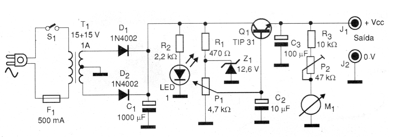
This power supply can provide adjustable output voltages between 0 and 12 V approximately, with a maximum current of 1 A, being ideal for powering projects under development or testing on a benchwork. In this source, we use a transistor as a serial regulator of the output voltage whose reference is provided by a zener diode.
The potentiometer adjusts the portion of the zener diode voltage to be applied to the transistor and thus the output voltage. A transformer with a secondary of less than 1 A (500 mA or 800 mA, for example) can be used, but this will become the maximum current supplied by the source.
In Figure 1, we have the complete diagram of this source.
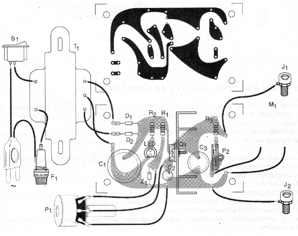
Several techniques can be used for assembly such as terminal bridge, printed circuit board, etc. For beginners, as few components are used, we give you an idea of how to do the assembly using a small printed circuit board isolated in Figure 2.

When assembling, observe the polarity of the diodes and electrolytic capacitors, as well as the position of the transistor. For the voltage output, use red and black terminals in order to identify the positive and negative poles.
Test and Use
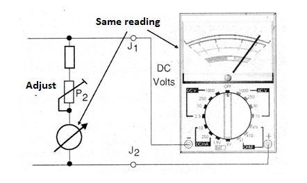
To monitor the output voltage, a 200 uA to 1 mA full scale analog indicator instrument can be used. This instrument can be calibrated based on the indications of a multimeter connected in parallel, as shown in Figure 3.

Adjust the source potentiometer to obtain an output voltage of 12 V, indicated by your multimeter. Then, adjust the trimpot in series with the instrument so that it goes to the end of the scale, where the 12 V voltage will be marked.
If the multimeter does not reach 12 V even with the pot open, check:
Whether the transformer actually supplies 15 V of the secondary.
Reduce the R1 value to 220 ohms.
If, when using the source, the transistor overheats and there is a sharp drop in the voltage indicated by the instrument at the output, it is a sign that the load requires a current greater than 1 A and cannot be powered by this source.
We also observed that this source does not have protection against shorts in its output, and the reader must take the utmost care with its use.
Q1 - TIP31 / A / B or C - Power NPN transistor
D1, D2 - 1N4002 - rectifier diodes
Z1 - 12V6 x 1 W - zener diode
LED1 - Common red LED
R1 - 470ohm x 1/8 W - resistor - red, yellow, brown
R2 - 2.2 kohm x 1/8 W - resistor - red, red, red
R3 - 10 kohm x 1/8 W - resistor - brown, black, orange
P1 - 4.7 kohm - linear or log potentiometer
P2 - 47 kohm - trimpot
C1 - 1 000 uF x 25 V - electrolytic capacitor
C2 - 10 uF x 16 V - electrolytic capacitor
C3 - 100 uF x 16 V - electrolytic capacitor
T1 - Transformer with primary according to the local and secondary network of 15 + 15 V x 1 A
M1 - 200 uA to 1 mA moving coil instrument
F1 - 500 mA - Fuse
S1 - Simple switch
J1, J2 - Red and black terminal blocks
Miscellaneous:
Printed circuit board or terminal bridge, power cable, heat radiator for the transistor, button for the potentiometer, fuse holder, mounting box, wires, solder, etc.


