

This circuit is used to test SCRs like the ones of TIC series. The simulation shows the power line half-cycles applied to a load. The load is an incandescent lamp.
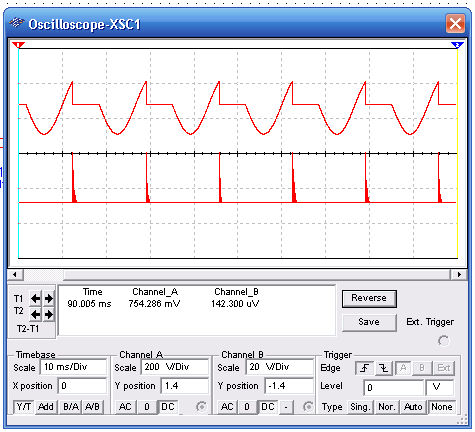
The wave shapes in the circuit can be displayed by the virtual oscilloscope of the MultiSIM. Observe the adjustments for a correct display. The upper signal is the voltage applied to the load and the lower signal are the trigger pulses produced by the diac.
To download the simulation files and Netlist - click here (ni0007.zip)


