This circuit wiII Iight a common fluorescent tube (from 7 to 40 watts) from a 6- or 12-volt power supply, such as ni-cad cells, D cells, car battery or other source, without need of a choke or starter.
Even the old tubes which no Ionger function at aII on AC power lines will Iight when used for this purpose. (Some of them, though, may be too weak to Iight when the circuit is powered from 6 or 12 volts. You should experiment beforehand).
You can use the device as an emergency Iight, in trailers, signaling, etc.
By powering the fluorescent Iamp with a transformer power supply you increase safety factor of an experiment, avoiding dangerous shocks or shorts.
Current drain, typically ranging from 100 to 800 mA, depends on the characteristics of the Iamp used, the power supply voltage, and the transformer.
The Iamp will brighten aocording to the drained current.
Experiments should be done with some different transformers and oscillatOr frequencies to get better performance out of the circuit.
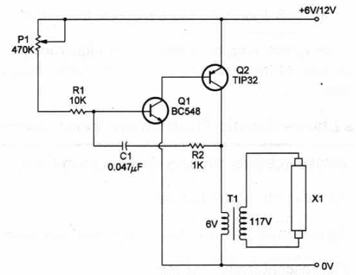
Basicaly, the circuit is a Iow-frequency oscillator driving a transformer.
High voltage is obtained from the transformer to Iight a fluorescent Iight.
The trimmer potentiometer allows frequency adjustment to get better performance.
Schematic diagram of the Fluorescent Lamp Inverter is displayed in Figure
1.

As you see, the circuit consists of a Iow-frequency oscillator with a pair of complementary transistors.
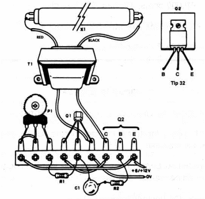
Components Iayout, using a terminal strip as chassis, is shown in Figure 2.

Components placement is not critical.
Transistor Q2 should be mounted on a Iarge heatsink.T1 is a 6V x 450 mA or 12 V x 450 mA transformer.
lf a CT (center-tapped secondary coil) transformer is you should use only two of the three secondary's wires.
Experiments with transformers with secondary currents from 300 to 800 mA and voltages betweeen 9 and 15V can be made to get better performance.
Warning: The fluorescent Iamp is powered with high voltages that can be dangerous.
Take care of the wires' insulations and when handling connections to the device.
Simple Fluorescent Lamp lnverter 4
Q1 - BCS48 - general purpose NPN silicon transistor
Q2 - TIP42 - PNP power transistor
T1 - Transformer: 117 VAC; 6 V x 450 mA or 12 V x 450 mA
X1 - Fluorescent Iamp - see text
P1 - 470,000 Ω - trimmer potentiometer
R1 - 10,000 Ω, 1/4-watt, 5% - resistor
R2 - 1,000 Ω, 1/4-watt, 5% - resistor
C1 - 0.047 µF - metal film capacitor
Ideas to Explore
To learn more about the circuit or to get better performance:
Try to use a ferrite transformer in place of T1. The circuit performance will increase.
Explain how transformers work in this kind of circuit and why transformers do not work in DC circuits.
Science projects and uncommon applications:
Replace X1 by an small ultraviolet fluorescent Iamp and you'll have a mineral ror fluorescent materials searcher. Many materials, including the ones with a high percentage of calcium, wiII giow when illuminated by ultraviolet. Many experiments and demonstrations can be made involving minerals, plants and fluorescent materials
An interesting experiment with plants is to study the effect of ultraviolet radiation on different plants' growth or germination. Irradiate several batches of various seeds, such as tomato, been, squash, etc., with UV, and then plant. Because of increasing UV radiation reaching the earth due to depletion of the ozone Iayer, the effect of this radiation on plant life is of concem to us alI.
Compare effects of different Iight wavelengths to seed germination. The wavelenghts of incoming solar radiation range to select seeds from common plants and expose differrent batches to UV and/or common Iight (red to blue). What happens with the diferent seeds during germination? You also can conduct the experiment not only with seeds, but plants and insects.
High voltage present in the 117V transformer coil can be used in nerve stimulation experiments. Please add a 10,000 ohm potentiometer to control the applíed voltage if the circuit ís intended to be used on humansl The voltage in the transformer has peaks as high as 400 V!
Fluorescent light can also be use in experiments with insects. Some kinds of insects are attracted by Iight (visible and ultraviolet!). Insect traps can be constructed using this circuit as base.
Fish and other animals can be attracted by tluorescent Iight. A circuit powered by cells or battery is important for fieldwork.
Alternate methods of farm pest control can use Iight, visible as well as radiation in the ultraviolet part of the spectrum. Insect traps can be constructed with fluorescent Iamp inverters.
Note: This circuit is part of the author’s book Fun Projects for the Experimenter Vol1 – TAB Books – 1998


