This circuit will produce intermittent beeps by a piezoelectric transducer when the temperature rises over a preadjusted value.
You can use this circuit in greenhouses, heaters, etc.
The sensor is a common silicon diode but an NTC can also be used if you change some components’ values.
Exchanging positions of Fit and P1 with D1 will cause the device to operate as an under-temperature alarm.
The intermittentsignal is generated by two oscillators. IC1a (pins 1,2 and 3) is an inverter that controls IC1 b and lC1c (oscillators).
lC1c (pins 8, 9 and 10) is a very-low-trequency oscillator that provides the modulation rate for the second oscillator.
The second oscillator (pins 5,6 and 4) has its frequency determined by R2 and C1.
The produced audio tone can be altered by adjusting both Cl and R2 within a large range of values.
Power comes from a 3- to 15-volt power supply.
For portable use a small 9- volt battery is recommended. Current drain is very low, about 0.5 mA when the tone is off.
When the tone is on, current drain rises to about 5 mA.
A schematic of the Over-Temperature Alarm is shown in Figure 1.

IC1, a 40933, has two gates operating as oscillators and two as buffer-inverters
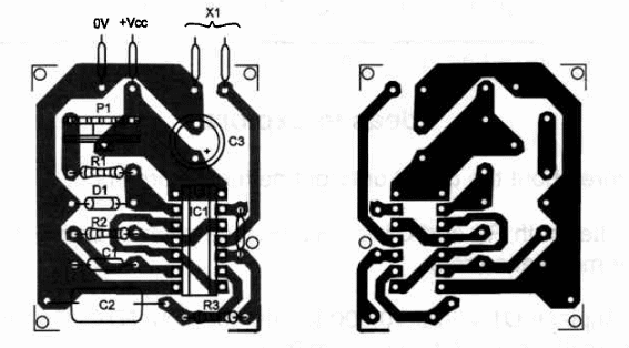
Components placement on a homemade printed-circuit board is shown in Figure 2.

You can made your prototype using a single-sided PC board.
Position of the polarized components, especially diode D1 (used as sensor), should be observed.
This sensor can be placed far from the device by using common wiring.
You must take some care to avoid humidity or water falling onto the sensor, which will cause adversely affect the alarm operation.
BZ is a piezoelectric transducer (Radio Shack 273-073 or equivalent) or a crystal earpiece.
Operation is adjusted by P1. Set this potentiometer to get sound at the desired temperature.
To get a more precise adjustment you can replace the common trimmer potentiometer by a multi-turn potentiometer.
Get the sensor between your fingers to see how it works: when the temperature rises some degrees the circuit will produce a serie of beeps.
Isolate the sensor, and after some seconds sound emission wiii stop.
Over-Temperature Alarm
lC1 - 4093 CMOS integrated circuit
D1 - 1N914 or 1N4148 general purpose silicon diode
BZ - Piezoelectric transducer or crystal earphone (Radio Shack 273-073 or equivalent)
R1 - 100,000 ohm, ¼ W, 5% resistor
R2 - 33,000 ohm, ¼ W, 5% resistor
R3 - 2,200,000 ohm, ¼ W, 5% resistor
P1 - 10,000,000 ohm trimmer potentiomer
C1 - 0.047 µF metal film or ceramic capacitor
C2 - 0.47 µF metal film or ceramic capacitor
C3 - 100 µF, 16 WVDC electrolytic capacitor
Ideas to Explore
To learn more about the circuit or to get better performance:
Alter both R2 and C1 to change tone pitch or both R3 and C2 to alter modulation rate.
Replace D1 with a 10,000 to 100,000 ohm NTC, R1 with a 2,200 ohm resistor, and P1 with a 100,000 to 1,000,000 ohm potentiometer, to get a new kind of sensor.
Try to add a powerful output audio stage using a transistor, such as a BD135 and a small loudspeaker. See other projects in this site for suggestions about the configuration.
Science projects and other applications:
Chemical processes that involve heat changes can be controlled using this alarm. The sensor should be protected against moisture and water in experiments involving liquids.
Replace D1 by an LDR or photodiode. The circuit will operate as a light alarm or dark alarm, depending upon sensor position. With an LDR it would be better to replace P1 with a 1,000,000 ohm potentiometer and R1 with a 10,000 ohm resistor. Lenses placed in front of the LDR or phototransistor can be used to increase sensitivity.
The circuit can also operate as a water-level alarm by using a two-wire sensor to replace D1. The sensor is made with two bare wires. The wires are separated by a distance of about 2 or 3 inches. The water completes the circuit while the wires are immersed. When the water level falls below the wires, the circuit is opened and the alarm is triggered.
Temperature in greenhouses, animal pens, incubators and aquariums can be monitored using this device. And it working with an LDR as the sensor, experiments involving light can be conducted.


