
This transmitter has a power output stage which, using common transistors reaches close to 2 watts. With a good external antenna, this power means a range of some tens of kilometers, depending of course on the topography and the sensitivity of the receivers used.
The power supply, which also influences the potency, can be made with voltages between 6 and 12 volts.
For 6 V, if batteries are used, they should be of the medium or large type, since the current being somewhat high can cause the rapid draining of small batteries.
The circuit has three settings: two of frequency and one modulation, all easy to make, requiring no special equipment.
The external modulation is made by an input where we can connect a common electret microphone with a polarization circuit, or the output of a mixer, where we will apply signals from different sources like other microphones, tape-deck, turntables, etc.
The coils determine the frequency range of operation that can typically be between 50 and 110 MHz. We therefore have a good part of the VHF band, including the FM band.
The table below allows you to select the coils according to the operating frequency ranges:
OPERATING FREQUENCIES
50-88 MHz
* L1 - 6 turns
* L2 - 4 + 4 turns enlaced to L1
* L3 - 6 + 6 turns
* L4 - 5 coils enlaced to L3
88 - 108 MHz
* L1 - 4 turns
* L2 - 3 + 3 turns enlaced to L1
* L3 - 4 + 4 turns
* L4 - 4 turns enlaced to L3
All coils are wound with the reference to a pencil. The wire used can be the ordinary coated 22 or enamelled from 20 to 24.
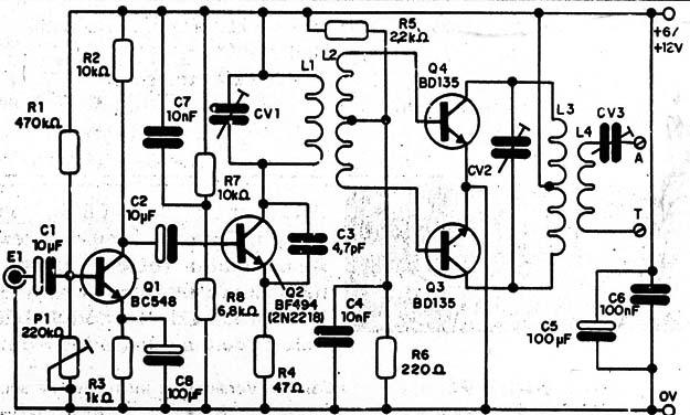
In Figure 1 we have the complete diagram of the transmitter.
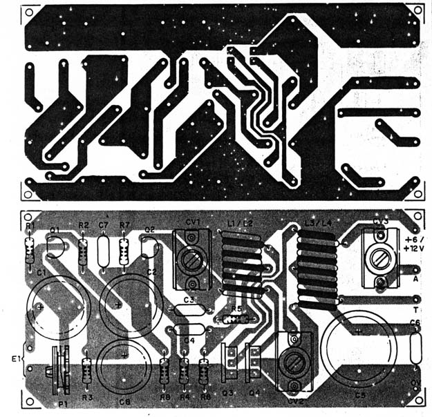
The arrangement of the components on a printed circuit board is shown in Figure 2.
The transistors allow equivalents, and for operation with 12 V, the transistors Q2 and Q3 must be equipped with heat radiators of at least 3 x 5 cm.
The CV1 and CV2 trimmers can be both plastic and porcelain based, with a maximum capacitance of 20 to 50 pF.
The smaller capacitors of the design must be ceramic and the larger electrolytes with higher working voltage than that used in the transmitter supply.
To adjust the transmitter we initially set CV1 to the desired frequency and then CV2 to obtain higher output signal strength. Adjusting CV2 may require retouching when adjusting CV1 to maintain frequency.
A field strength meter or a small 6 V x 50 mA lamp can be used to evaluate the signal strength.
The antenna must be connected to the circuit via the appropriate cable and in CV3 we make the final adjustment for greater efficiency, now with the antenna connected.
In the trimpot we adjust the modulation so that the sound comes out clear and without distortion, according to the signal source.
If the power supply is used it must have excellent filtration so that rumbling does not occur. If the transmitter and the source are built in separate metal boxes, we will have less possibility of rumbling in the transmission.
Semiconductors:
Q1 - BC548 or equivalent - general purpose NPN transistor
Q2 - BF494 for 6 V supply; 2N2218 or BD135 for 12 V power supply
Q3, Q4 - BD135 or BD137 - medium power NPN transistors
Resistors: (1/8 W, 5%)
R1 - 470 k ohm - yellow, violet, yellow
R2 - 10 k ohm - brown, black, orange
R3 - 1k ohm - brown, black, red
R4 - 47 ohm - yellow, violet, black
R5 - 2.2 k ohm - red, red, red
R6 - 220 ohm - red, red, brown
R7 - 10 k ohm - brown, black, orange
R8 - 6.8 k ohm - blue, gray, red
P1 - 220 k ohm - trimpot
Miscellaneous:
L1 to L4 - coils - see text
A printed circuit board, assembly box, Q3 and Q4 heat radiators, wires, welding, power supply or battery holder, etc.


