
Here we have an interesting version of a temporized alarm which can use the most diverse types of sensors. Once activated it keeps triggered an alarm circuit for a time set in P1. This time can range from a few seconds to about 20 minutes depending on the value of C2 which at most can have 470 µF and P1 which at most can have 1 M.
See the formula for the first temporized alarm that is the same for this circuit. (See the formula in the math section of the site)
The device is powered by 4 medium or large alkaline batteries and in standby condition its power consumption is very low.
The complete circuit is given in Figure 1.
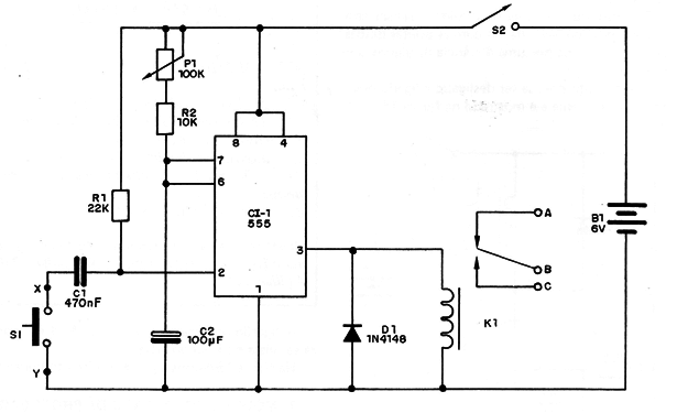
One touch at the pressure switch (NO) and the alarm will fire for a time depending on the setting of P1.
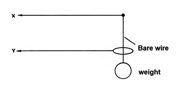
For S1 we can use a switch coupled to doors or windows, a reed-switch that in this case is activated by the approximation of the magnet and not by its withdrawal or even a pendulum sensor, as shown in Figure 2.
The alarm also allows the connection of sensors in parallel, each of which can activate the alarm independently.
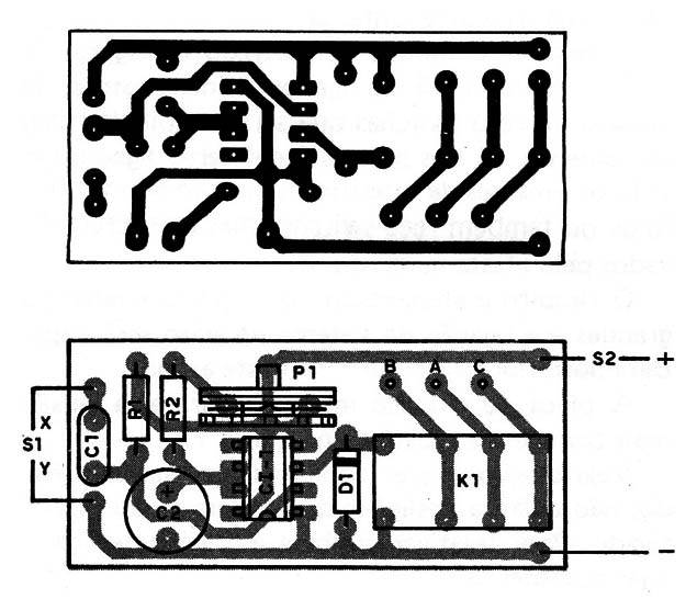
In Figure 3 we give the printed circuit board.
CI-1 - 555 - integrated circuit
D1-1N4148 or 1N914 - silicon diode of general use
K1 - 6 V relay
P1 - trimpot or potentiometer of 100 k
S1 - pressure switch or sensor
S2 - single switch
B1 - 6 V - 4 medium or large batteries
C1 - 470 nF (474) - ceramic capacitor
C2 - 100 µF X 12 V - electrolytic capacitor
R1 - 22k X 1/8 W - resistor (red, red, orange)
R2 - 10k X 1/8 W - resistor (brown, black, orange
Miscellaneous:
A printed circuit board, connection wires, assembly box, support for 4 alkaline batteries, etc.


