An astable multivibrator, put to work by using it as a source of clock pulses for a 4017 counter, is the basis for this circuit.
We can use it to generate random numbers in a range of one-of-ten or as a 0-to-9 counter in science projects or in other applications.
You can also adjust the clock so that it supplies one pulse each second for using the circuit as a timer in scientific experiments or at home.
If you alter the clock pulse frequency, time range can be changed so that it supplies one pulse each minute or ten minutes. In this case, the time range will rise to 9 minutes or 90 minutes (in 1- or 10-minute steps).
As a sequence generator in logic circuits demonstrations, you can change the astable operation of the 555 to monostable, connecting a momentary switch or any sensor that can be used to trigger it.
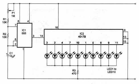
The circuit can be powered from 6 to 12 V supplies, and R3 depends upon the voltage of the power supply.
Use a 470 ohm resistor if the supply voltage is 6 V. Use a 1,000 ohm resistor if the power supply used is 12 V.
Capacitor C1 determines the pulse rate range and can be altered. Values between 1 and 1,000 µF can be used. Remember that higher values mean lower pulse rate.
P1 adjusts the pulse rate within 100:1, depending on the capacitor used.
Figure 1 shows the schematic diagram of the sequence Generator.

The circuit uses a 555 IC timer to generate the clock pulses and a 4017 CMOS IC, a counter and 1-of-10 decoder to drive ten LEDs as indicators.
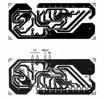
Components placement on a homemade printed-circuit board is shown in Figure 2.

You can also use a solderless board or breadboard to mount it.
Positions of the polarized pieces, such as the LEDs and electrolytic capacitor, should be observed.
Sequence Generator
IC1 - 555 - Integrated circuit, timer
IC2 - 4017 - CMOS Integrated circuit, counter
LEDs - Common red, yellow or green
P1 - 1,000,000 Ohm potentiometer
R1, 2 - 10,000 ohm, 1/4W, 5% resistors
R3 - 470 ohm, 1/4W, 5% resistor
C1 - 10 µF/16 WVDC electrolytic capacitor
Ideas to Explore
To learn more about the circuit or to get better performance:
Wire a momentary switch between lC1’s pin 3 and lC2’s pin 14 to control the counter. You can stop the counter any time with this switch.
Explain how counters such as the 4017 work.
Could you alter the circuit so that it counts to any value between 2 and 9?
Science and uncommon uses:
Wire the 555 as a monostable multivibrator and use an LDR as sensor to trigger it. The circuit will operate as a pulse-of-light counter.
Use this circuit in a project about computers. You can produce pulses to be counted using the experimental flip-flop described in this book.
Experiments on ESP (Extra-Sensory Perception) can be conducted using this circuit. Random numbers in a scale of 1-to-10 can be generated using this circuit.


