A complete radio AM receiver which requires no battery power at all can be created, with a few components.
The classic circuit of the well-known crystal radio or crystal receiver can be based on a germanium diode as detector, or it you prefer, the original galena crystal.
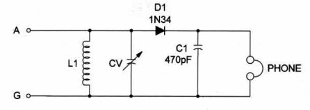
Figure 1 shows the classic circuit.

L1 is a proprietary antenna tuning coil wound on a paper tube and C1 is a matching variable capacitor (365 to 500 pF).
A variable capacitor can be found in old non-working transistor radios.
You can also find the diode in these sets and use it for this project.
Virtually any diode can be used, and the only other circuit component is capacitor 01, connected across the output.
The earphones must be a highimpedance type (headphones).
An external aerial and good physical ground connection is essential for good reception.
The circuit will tune AM band radio stations not far from your home.
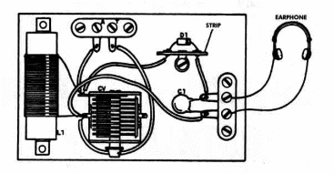
Component layout is shown in Figure 2.

L1 is formed by 100 turns of No. 22 to 28 AWG enamelled wire on a 1-inch diameter paper tube.
Crystal Radio
D1 - 1N34 or any germanium diode
L1 - Coil - see text
CV - 365 to 500 pF variable capacitor
C1 - 470 pF ceramic capacitor
PHONE - High-impedance (2,000 to 10,000 Ω) phone
Ideas to Explore
To learn more about the circuit or to get better performance:
Use an audio amplifier to get better reception.
Replace the coil by 100 turns of No. 22 to 28 wire on a ferrite rod
Science projects:
This set can be used to demonstrate how old-time radio receivers operated. Explain how a galena detector works.


