This circuit can be used to reinforce weak audio signals coming from several sources as transducers (microphones, guitar pick-ups or vibration sensor), sensors or experimental radios. In an important application he can be placed between the input of your PC or an audio amplifier and the microphone to increase the sensibility. The circuit is very simple and compact allowing its installation inside the own audio source or the amplifier.
Note: this circuit is part of my book Science Fair and Technology Education Projects.
Considering the current drain is very low it can be powered by AAA, AA cells or even by a 9 V battery.
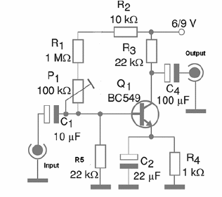
The output signal level depends on the gain and on the amplitude of the input signal. In this case the amplification gain is around 50 times, but it can be changed by the replacement of R1 and by the P1 adjustment. This Potentiometer or trimmer Potentiometer is placed just to allow gain adjustments according to the signal source, avoiding saturation and distortion.
The adjustment is necessary to find the output signal level that can excite properly the external amplifier.
It is also necessary to alert the reader that they work with low level audio signals, so appropriate shielding is necessary to protect the circuit against external noise and other interference able to affect the signal integrity. Figure 1 shows the complete diagram for the amplifier.

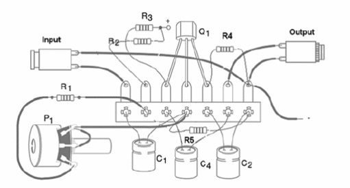
Figure 2 shows the components placement on a terminal strip.

The reader can also assemble the circuit on a printed circuit board (PCB) with best results and a more compact version. Remember that if you intend to use the unit to amplify stereo signals, you will need two channels or two pre-amplifiers like the one described.
The connections and the component terminals should be as short as possible to not pick up noise and hum. The transistor BC549 gives larger signal gain and low level of noise, but in common applications it can be replaced by easier-to-find types as the BC548 and BC547.
The resistors are 1/8 W x 5% types, and the electrolytic capacitors are rated to a WVDC (Working Voltage DC) of 12 V or more. In order to test the unit, plug it to the AUX input of any amplifier and apply a signal to the input, adjusting P1 to the best performance.
Semiconductors:
Q1—BC549 or equivalent—Low noise, high gain silicon NPN transistor
Resistors: (1/8 W, 5%)
R1— 1 MΩ—brown, black, green
R2—10 kΩ—brown, black, orange
R3, R5—22Ω—red, red, orange
R4—1 kΩ—brown, black, red
P1—100 kΩ—Potentiometer—lin or log
Capacitors
C1—10 uF x 6 V—electrolytic
C2—22 uF x 12 V—electrolytic
C3—100 uF x 12 V—electrolytic
Other:
S1—On/Off switch
B1—6 V or 9 V—4 AA cells with holder or 9 V battery with connector
J1, J2—Input and output jacks - also can be used a plug for J2
Terminal strip or printed circuit board, plastic box, shielded cables, knob for the Potentiometer, wires, solder, etc.


