This circuit is indicated to people starting from 10 years old, but with an adult supervision. Recommended to technical and engineering courses. This device produces high voltage from common cells being able to cause a heavy shock to any person that touches its output. If the output is connected to any object isolated from the soil, this object will be electrified.
In a science fair, or for shows, this circuit can be used to explain how transformers work and also the high voltage inverters. Inverters are devices that allow the use of common cells or a car battery to power a fluorescent lamp or some low power appliances, normally powered from the AC power line. Since the circuit is experimental, the current drain is very high, draining the cells in a short time if connected by long periods of time.
The project consists basically in a small inverter powered by 4 AA or C cells. The recommended transformer has a 220 V or 110 V wound, but the output voltage can rise above these values, since the wave shape of the signal is not sinusoidal (like the voltage found in the AC power line). The voltage peaks can reach 200 or 400 V, depending on the transformer.
How it Works
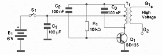
A transformer can change voltage, stepping it up or down according to the number of turns of its coils. So, if a transformer has 100 times more turns in its primary than in the secondary, the voltage applied to the primary will step down 100 times, and if applied to the secondary will step up 100 times. In our project, if you apply 1.5 V to the secondary, the output voltage will be 150 V (or more, if the voltage is not sinusoidal).
Observe that we could either apply the voltage to the primary and take the output in the secondary, or apply the voltage to the secondary and have the output in the primary. We just chose the second option in this project.
Otherwise, it is very important to remember that the transformer does not work with direct currents (DC), like the ones sourced by cells and batteries. The currents may have fast changes to induce voltages in the other winding.
Therefore, transformers are only used in AC circuits in normal conditions. In order to use a transformer in a DC circuit, powered by cells or batteries, for instance, we need a configuration to produce current changes. This project uses a transistor wired as an oscillator. This oscillator produces fast changes in the current, inducing high voltages in a common transformer.
How to Build
Figure 1 shows the schematics for the high voltage generator using a common transistor and a step up transformer.

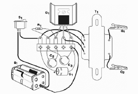
The components can be placed on a terminal strip or printed circuit board. Figure 2 shows how the components are soldered to a terminal strip.

The transistor should be assembled on a small heatsink. Equivalents can be used, such as the BD135 or BD137. The resistor is a 1/8 W or greater with tolerances starting from 5%. C1 is an electrolytic capacitor with a WVDC (Working Voltage DC) of 12 V or higher.
The other capacitors can be polyester or ceramic. The transformer has a primary wound rated to 110 or 220 V and a secondary with voltages in the range between 6 and 12 V and currents up to 500 mA.
Testing and Using
To test, place between your thumb and forefinger G1 and G2 and press S1for a moment. You will feel a strong shock. Using is very easy. You just have to connect G1 to the object to be electrified and G2 to any object connected to the ground, such as a metal bar, a metallic structure of a building, etc.
Pressing S1 the object will be electrified. If you notice low performance, change the value of R1. This component can assume values in the range between 4.7 k? and 47 k? .
What to Explain
Explain the way a transformer works. Show that the transformer needs changes in the current to operate. Show how inverters function and how they are used. Introduce the concept of energy transformation, showing that energy cannot be created, but only transformed. And with that, conclude saying that if you increase the voltage, the current is decreased by the same ratio.
Other Uses
Coupled with a touch switch or some other sensor, this circuit can be used to protect an object or a place, turning on when someone activates the sensor. The circuit can also be used to power a small fluorescent lamp (5 to 15 W) from common cells. But, remember: the current drain is high when powering lamps, so the cells’ life is not long.
Semiconductors:
Q1—BD135 or equivalent—Medium power silicon NPN transistor
Resistor: (1/8 W, 5%)
R1—10 k?—brown, black, orange
Capacitors:
C1—100 ?F x 12 V—electrolytic
C2—22 nF (223 or 0.022) - ceramic or polyester
C3 = 100 nF (104 or 0.1) - ceramic or polyester
Other:
B1—6 V—4 AA or C cells with holder
S1—On/Off switch
T1—Transformer—primary 110/117/220 or 240 V—secondary—6 to 12 V—up to 500 mA
G1, G2—Alligator clips
Terminal strip or printed circuit board, plastic box (optional), heatsink for the transistor, wires, solder, etc.


