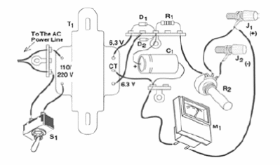
The power supply shown by figure 1 is a very simple configuration recommended to the experimenter and the designer that want to power small devices with current drains up to 50 mA.

The power supply can source voltages in the range between 0 and 9 V, with the value adjusted by a common Potentiometer. Figure 2 shows how the components are placed in the final assembly, using terminal strips as a chassis for the small pieces.

As explained, this circuit is very simple, and does not use any device to regulate the voltage, like a zener diode or an integrated circuit. The output voltage is adjusted by a Potentiometer. This configuration causes some problems to variable current loads.
The voltage changes with the current. So the circuit is recommended only for low current applications where the current can be adjusted and do not change with the time or other causes. To control the output voltage we recommend the use of a low cost Voltmeter (M1) or plug a Multimeter in the DC Volt scale.
With luck, you can find an instrument like that in some non-functioning appliance. A low cost Multimeter can be used for this task.
Using it is very simple. Plug the device to be powered to the output of the power supply, observing the poles. Then, put the Potentiometer at the minimum voltage (all to the left) and turn on the power supply. The next step is to adjust P1 to the desired voltage in the output.
We cannot add a voltage calibrated scale, because the adjustment depends on the current sourced to the load. Do not power electronic circuits that are sensitive to voltage changes. The circuit is suitable for power lamps, small DC motors, electromagnets, solenoids, electrochemistry experiments, etc.
D1, D2—1N4002 or equivalent—silicon rectifier diodes
T1—Transformer—primary according the local AC power line voltage and secondary rated to 6 + 6 V (CT) x 250 to 300 mA
C1—1,000 uF x 12 V—electrolytic capacitor
R1—10 ohm x 2 W - wire wounded resistor
P1—50 ohm —wire wounded Potentiometer
M1—Voltage meter 0-9 V or 0-12 V—see previous text
S1—On/Off switch
J1, J2—Output terminals
Other:
Terminal strips, plastic or metallic box, power cord, knob for the potentiometer, wires, solder, etc.


