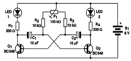
This circuit uses only two transistors and some other common components. The circuit consists in a multivibrator that makes two LEDs turn on and off in an alternate way. The device can be used as a false alarm, signaling, or even in robots, miniatures, toys and mechatronic devices for decoration.
Note: this project is part of my book Science Fair and Technology Education Projects published in USA.
The LEDs are triggered by the change of state of the two transistors. The turn on and off cycle is determined by the capacitors and by the adjustment of P1. The trimmer Potentiometer or the Potentiometer can assume values between 22 kΩ and 100 kΩ and the capacitor can range from 2.2 uF to 100 uF.
The higher the capacitor, the longer will be the commutation cycle of the transistor.
The transistors are any general purpose types, including the ones found in old non functioning appliances. All you have to do is test them. The power supply is formed by 4 AA cells or a 9 V battery. Figure 1 shows the schematic diagram for the project.

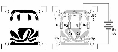
Figure 2 shows the components placed on a small printed circuit board (PCB).

This assembling technology is recommended for more experienced readers who have resources to etch their own printed circuit boards. Beginners can assemble the project using a terminal strip.
The device can be housed inside a small plastic box. When assembling, be careful with the LEDs’, transistors’ and capacitors’ positions, since they are polarized. To test the device, install the cells into the cell holder. Since there is no on/off switch, the LEDs will begin to blink immediately. If you intend to add more LEDs, connect them in series. The number is limited by the power supply voltage. Using a 6 V supply, the number is 3 for each side. Using 9 V the number rises to 5.
To change the frequency, use P1 and, if you don’t reach a desirable rate, replace C1 and C2. Make experiments with these components to find the best performance. If LEDs are placed in parallel, add a 220 to 330 ? resistor in series with each one.
Semiconductors:
Q1, Q2—BC548 or equivalent—general purpose silicon NPN transistors
LED1, LED2—Common LEDs—any color
Resistors: (1/8 W, 5%)
R1, R4—330 Ω —orange, orange, brown
R2, R3—10 kΩ—brown, black, orange
P1—100 kΩ—trimmer Potentiometer or common Potentiometer—lin or log
Capacitors:
C1, C2—10 uF x 6 V—electrolytic
Other:
B1—6 V—4 AA cells or a 9 V battery
Printed circuit board, cell holder or battery connector, wires, plastic box, solder, etc.


