
This transmitter can produce telegraph signals that will be received on a common AM radio. With an antenna 2 to 3 meters long the range will reach a few tens of meters. We remember that in this range, to get a range of hundreds of meters we need much more power and a good antenna.
The circuit is experimental, transmitting telegraphic signals that are coded by a manipulator. Thus, a short touch represents a point and a long touch a stroke. The combination of dots and dashes results in letters, numbers and other symbols according to the Morse Code.
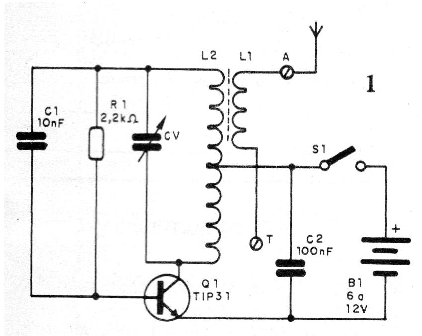
We can use this circuit in demonstrations and for telegraphy training. In figure 1 we have its diagram.
The arrangement of the components on a terminal strip is given in figure 2.
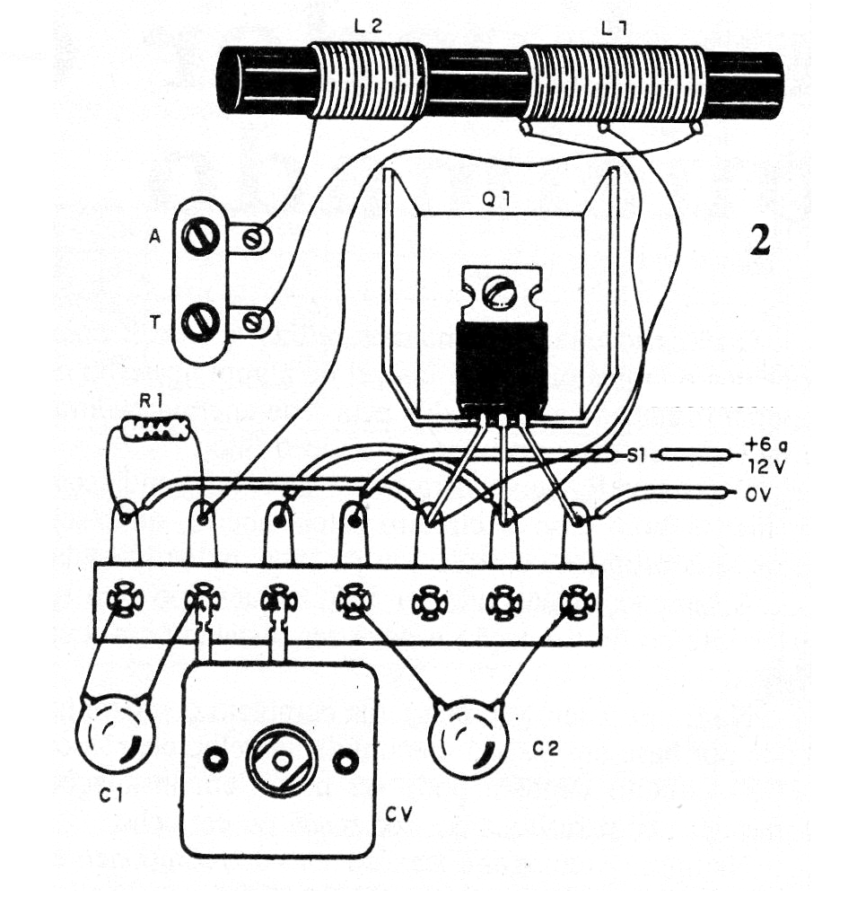
For higher power the circuit can be powered with 12 V from large batteries or power supplies. The transistor must be equipped with a heat radiator.
For the medium wave band L1 is formed by 40 + 40 turns of wire 28 on a ferrite rod and L2 20 turns on L1. The number of turns for shortwave operation can be reduced.
The variable capacitor can be obtained from an out-of-use AM radio.
List of Material:
Q1 - TIP31 - NPN power transistor
L1, L2 - coils, see text
CV - variable for AM
S1 - Telegraphic manipulator
B1-6 to 12 V - batteries or power supply
R1- 2.2 k ohm - resistor - red, red, red
C1- 10 nF - ceramic capacitor
C2- 100 nF- ceramic capacitor
Miscellaneous:
Terminal strip, battery holder or source, transistor radiator, ferrite rod, antenna (long wire), mounting box, wires, solder, etc.


