
If you need voltages from 1 to 12 V with current up to 1 A from a fixed higher voltage source up to about 20 V, for example, the regulator described in this article, is an interesting solution.
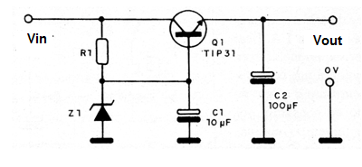
The circuit consists of a regulator with a zener diode. The values of some components depend on the voltage we want at the output.
Thus, the zener diode must have a voltage 0.6 V higher than the desired output voltage. For example, to get 1.5 V, we use a zener of 2.1 V. To get 12 V we use a zener of 12.6 V.
The resistor R depends on the difference between the input voltage and the output voltage, as shown in the following table:
Voltage difference R
2 to 6 V 220 ohm
6 to 9 V 330 ohm
9 to 12 V 470 ohm
In figure 1 we have the regulator diagram.
In figure 2 we have the arrangement of the components in a terminal strip.
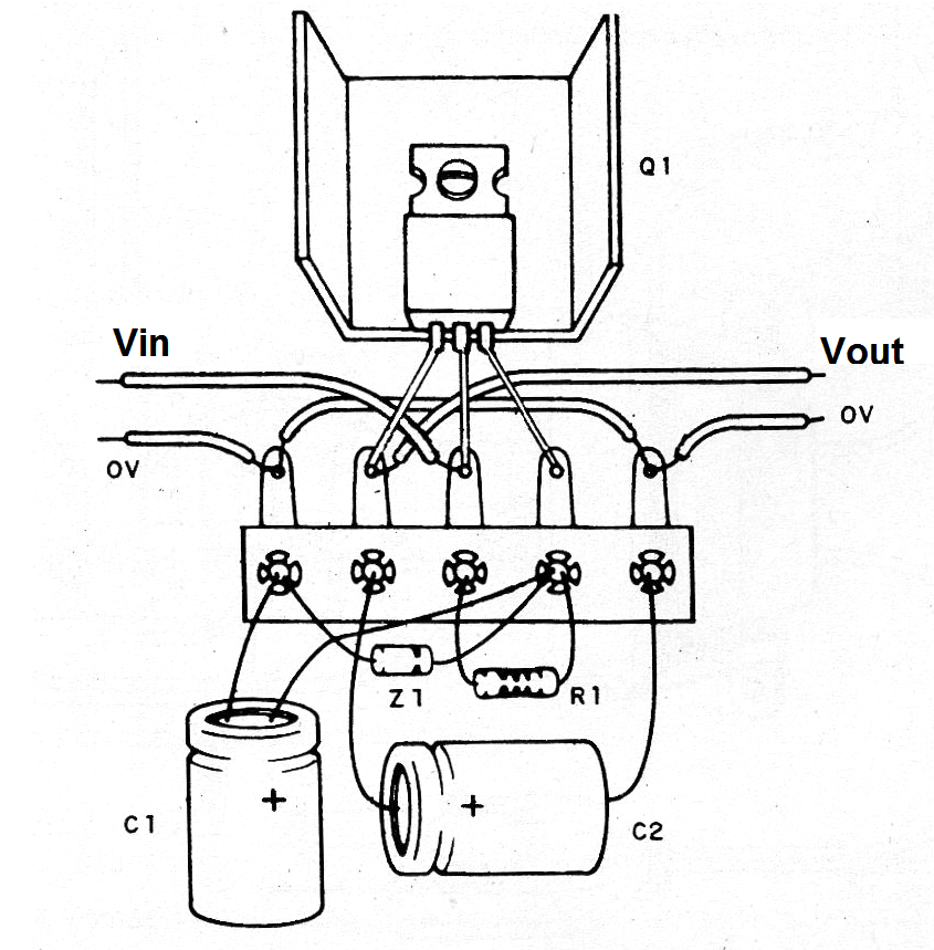
The transistor must be equipped with a heat radiator. The BD135 can be used for currents up to 500 mA. Electrolytic capacitors must have a working voltage 50% higher than the input voltage.
Material list:
Q1- TIP31 - NPN power transistor
Z1- Zener diode from 400 mA to 1 W - see text
R1- ¼ or ½ W resistor - see text
C1- 10 uF - electrolytic capacitor
C2- 100 uF - electrolytic capacitor
Miscellaneous:
Terminal strip, heatsink for the transistor, wires, solder, etc.


