
We present a simple LED blinker with extremely low consumption using the CMOS version of the 555. The circuit can operate with voltages from 3 to 6 V and even 12 with the increase of the resistor in series with the LED.
The well-known 555 integrated circuit has an ultra-low-power CMOS version that is TLC7555 or TL555.
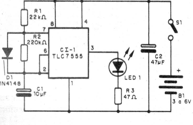
The circuit has nothing different from the normal version with the 555 bipolar observing only the presence of a diode to obtain a very low active cycle.
The frequency depends on R1 and R2 and the capacitor.
In figure 1 we have the complete diagram of the blinker.
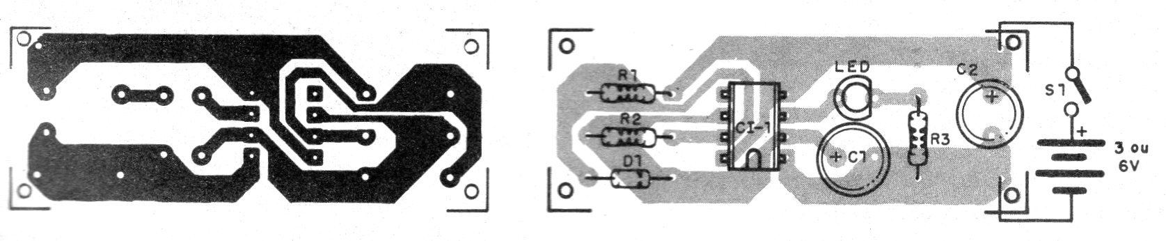
In figure 2 we have the printed circuit board for this assembly.
The resistors R1 and R2 can be changed to change the speed of the blinks.
The consumption is of the order of microampères, what guarantees a great durability for the batteries or battery used in the feeding.
Material list
CI-1 - TLC7555 or CMOS version of the 555 - integrated circuit
D1 - 1N4148 - silicon diode
LED - red LED or any ordinary
S1 - Single switch
B1 - 3 to 9 V - batteries or battery
R1 - 22k ohms x 1/8 W - resistor - red, red, orange
R2 - 220 k ohms x 1/8 W - resistor - red, red, yellow
R3 - 47 ohms x 1/8 W - resistor - yellow, violet, black
C1 - 10 uF x 6 V - electrolytic capacitor
Several:
Printed circuit board, battery connector or battery holder, wires, solder, etc.


