
Component testing can be done easily with a device called a continuity tester. This instrument verifies if a component leaves or does not pass an electric current, thus allowing an evaluation of its state.
Of course you need to know if the good component should or should not let the current flow through. Thus, a resistor lets the current flow in an inverse proportion to its value while a coil or a transformer must have continuity in its windings, letting the current through.
On the other hand, a diode should pass the current in one direction, but not in the opposite direction, and a capacitor must be insulated, not letting the current through.
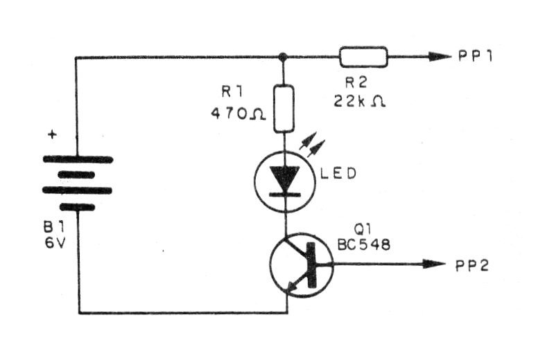
The tester we present has a great sensitivity, causing the LED to light up with resistances less than 100 000 ohms. In Figure 1, we have the circuit of this fitting which can use any transistor of general use.
Assembly of the components based on a small terminal strip is shown in Figure 2.
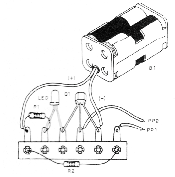
By leaning one probe on the other, the LED should light, indicating the current flow.
Material list
Q1 - BC548 - NPN general purpose transistor
LED - common red or other colored LED
B1 - 6 V - 4 small batteries
R1 - 470 ohms x 1/8 W - resistor - yellow, violet, brown
R2 - 22k ohms x 1/8 W - resistor - red, red, orange
Miscellaneous: battery holder, deterministic bridge, probes, wires, welding, etc.


