
In Figure 1 we have a circuit of a pulse generator built around one of the four voltage comparators in the LM339 integrated circuit.
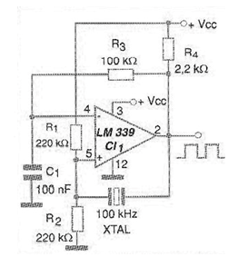
The relationship between the interval between the pulses and their duration is given by the ratio of values between R1 and R2. Capacitor C1 determines the operating frequency that can have a maximum of about 1 MHz for this circuit.
The use of a voltage divider at the reference input enables the use of a single source instead of a symmetric source. For the values of components given in the figure, the generated frequency will be of some kHz, observing the tolerances.
In figure 2 we have a suggestion of printed circuit board taking advantage of one of the comparators. The others can be used in other functions.
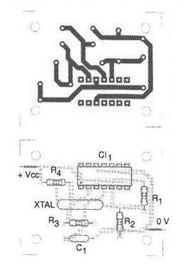
The power can be made with voltages from 3 to 12 V typically. Other types of comparators and even operational amplifiers can be used in the same circuit.
Material list
CI-1 - LM339 or equivalent - quadruple voltage comparator
D1 - 1N4148 - general purpose diode
R1 - 150 k ohm x 1/8 W - resistor
R2 -22 k ohm x 1/8 W - resistor
R3, R4, R5 - 100 k ohm x 1/8 W - resistors
C1 - 10 nF - ceramic or polyester capacitor
More:
Printed circuit board, power supply, wires, solder, etc.


