
This experimental receiver has some interesting features for presentation at fairs, exhibitions or even for those who want something different: the energy that feeds the amplifier stage comes from the very signal picked up by the antenna.
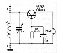
The circuit uses a germanium transistor and the junction of the transistor itself functions as a detector. The antenna must be very long so that the signals captured have enough intensity to power the circuit.
The range captured is medium wave. The coil consists of 100 turns of wire 28 or nearly, on a ferrite rod. The variable capacitor can be obtained on any out-of-use AM radio.
The headphone must be high impedance, or a piezoelectric crystal earphone or a capsule with a 4k7 resistor connected in parallel may be used. Germanium transistors of any type can be used, NPN or PNP.
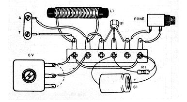
In Figure 1, we have the complete diagram of the receiver and in Figure 2, its assembly made in a small terminal bridge.
Grounding can be done in a buried bar or any large metal object, such as door and window frames.
Material list
Q1- 2SB75, OC74 or any old germanium transistors
R1- 12 k ohms x 1/8 W - resistor - brown, red, orange
C1 - 1 uF - electrolytic capacitor - 6 V or more
L1 - Coil - see text
CV - Variable capacitor - see text
Miscellaneous: handset, terminal strip, telephone jack (optional), antenna, wires, welding, etc.


