
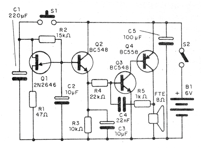
When we tighten and release S1, the circuit produces a sound similar to a prolonged laughter whose realism will depend on the choice of components R2, R3 and R4 to be done experimentally, around the indicated values.
Mounted in a box, it can be used in toys and other applications. We put this circuit in a box with a remote control and put it under a Christmas tree. As the children approached, the control was triggered and a good laugh made them intrigued, imagining a hidden Santa.
The circuit is simple to assemble and can work with 4 batteries or a battery. In Figure 1, we have the complete diagram of the electronic laugh.
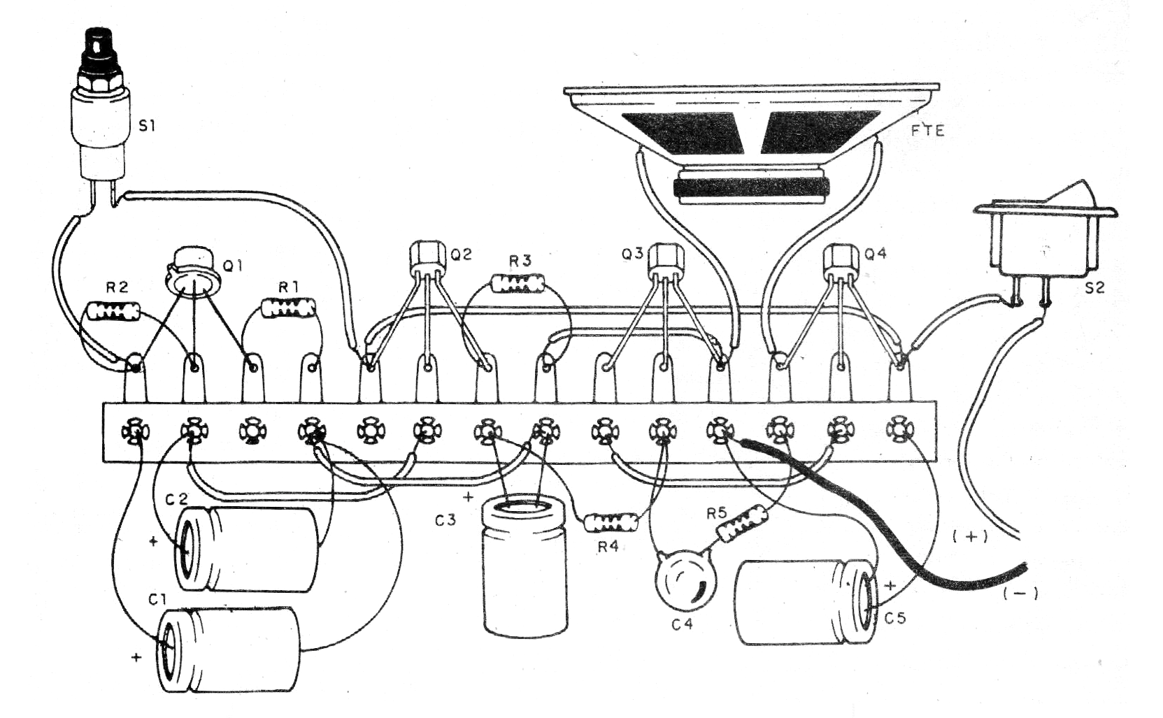
A simpler didactic assembly can be made on the basis of a bridge of terminals, as shown in Figure 2. However, for a better and more compact version, one can use a printed circuit board. Assembly on a breadboard is also interesting.
In the assembly, observe the position of the transistors, especially of the transistor unijunction which does not admit equivalents. The polarity of the battery is also important.
Material list
Q1 - 2N2646 - unijunction transistor
Q2, Q3 - BC548 - general purpose NPN transistors
Q4 - BC558 - PNP general purpose transistor
R1 - 47 k ohms x 1/8 W - resistor - yellow, violet, orange
R2 - 15k ohms x 1/8 W - resistor - brown, green, orange
R3 - 10 k ohms x 1/8 W - resistor - brown, black, orange
R4 - 22k ohms x 1/8 W - resistor - red, red, orange
R5 - 1k ohms x 1/8 W - resistor - brown, black, red
C1 - 220 uF x 12 V or more - electrolytic capacitor
C2, C3 - 10 uF x 12 V or more - electrolytic capacitors
C4 - 22 nF - polyester or ceramic capacitor
C5 - 100 uF x 12 V or more - electrolytic capacitor
S1 - Pressure switch NA
S2 - Single switch
B1 - 6 V - 4 common batteries
FTE - Speaker 8 ohms x 5 cm or bigger
Miscellaneous: terminal strip, battery holder, mounting box, wires, welding, etc.


