
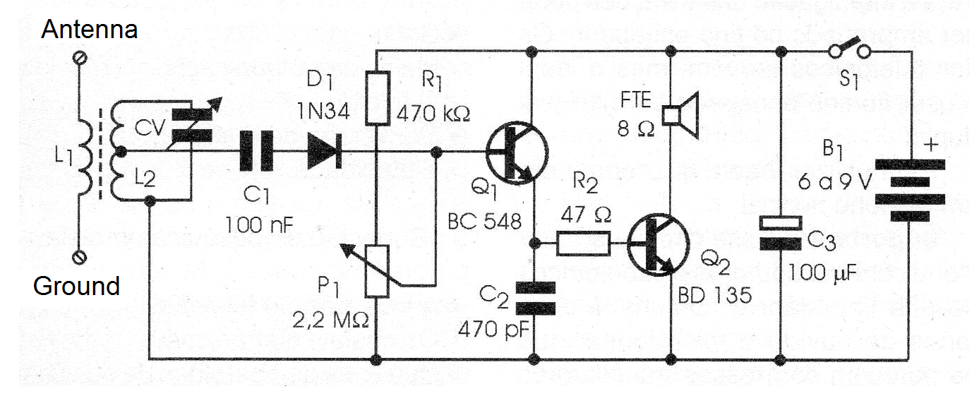
If the first assembly of many readers is a radio, it should be simple and moreover, not require complicated adjustments. The following circuit is ideal for beginner readers, students and even teachers who want to use this topic in an elective course.
It also serves those who wish to have their first radio, assembled by their own hands in a simple way and even taking advantage of scrap components such as the ferrite stick, the speaker and the CV variable capacitor.
The described receiver tunes, with good sensitivity, the local stations of average waves. For the weaker it needs an antenna that is nothing more than a piece of ordinary wire from 2 to 20 meters in length and a ground connection made in a water pipe or any large metal object, or simply Holding the wire between his fingers.
The power supply for the device can be batteries, battery or power supply of 6 to 9 volts. In the case of the battery, we do not recommend the small types since the high consumption of the circuit exhausts them quickly. For 9 V we recommend the use of medium batteries or a source.
In Figure 1 we have the receiver diagram.
The assembly can be made from a bridge of any type, which will be fixed in a base of wood or plastic as shown in figure 2.
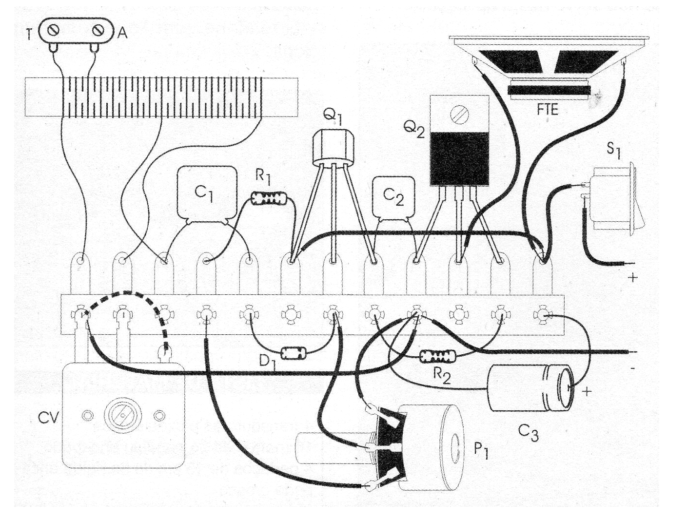
The coils are wound onto a ferrite stick, which can be harnessed from some out-of-use radio. This stick should be at least 15 cm long. L1 is formed by 10 turns of wire between 22 and 28 AWG and L2 by 40 + 40 turns of the same wire.
To make this coil we wind 40 turns of wire, taking a plug or tap and then wrap another 40 turns of wire in the same direction.
The CV variable capacitor can be of any type for medium-wave radios. The speaker can be of any type or size.
P1 is a potentiometer of non-critical value, between 1.5 M ohms and 4.7 M ohms. This potentiometer adjusts the bias of the circuit to obtain the highest gain without distortion acting as well as a sensitivity and volume control.
The transistors allow equivalents as well as diode D1. The other components have the specifications given in the material list
Unsing the receiver: connect it to a good antenna and press S1. Set CV and P1 at the same time to capture the strongest local stations.
Adjust for best reception. If in your locality the strong stations are at near frequencies, with a tendency to "mix" in this receiver, change the coil by twisting it with 20 + 60 turns (20 turns being on the side of the earth). With this, the receiver will have greater selectivity.
If the lower frequency stations are not picked up, make the dotted connection shown in figure 2, interconnecting the two sections of the variable capacitor.
For greater volume and sound quality, the speaker should be placed in a small speaker that can be improvised even with a cardboard box.
PARTS LIST
Semiconductors:
Q1 - BC548 or equivalent - general purpose NPN transistor
Q2 - BD135 - medium power NPN transistor
D1 - 1N34 or equivalent - germanium diode
Resistors: (1/8 W, 5%)
R1 - 470 k ohms - yellow, violet, yellow
R2 - 47 ohms - yellow, violet, black
P1 - 2.2 M ohms - potentiometer
Capacitors:
C1 - 100 nF - ceramic
C2-470 pF - ceramic
C3 - 100 uF / 12 V - electrolytic
CV - Variable up to 410 pF - medium-wave radio
Miscellaneous:
L1, L2 - Coils - see text
FTE - 4/8 ohms - 5 to 10 cm - common speaker
S1 - Single switch
B1 - 6 to 9 V - common batteries
Terminal bridge, mounting base, ferrite rod, buttons for variable and potentiometer, battery holder, enameled wires, antenna, etc.


