
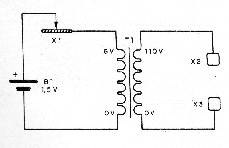
This circuit generates high voltage, but harmless discharges, due to the low intensity of the current and short duration. The shocks are given in which to hold the electrodes X2 and X3. For the drive the operator must scrub the tip of the wire P in the file in order to close the circuit, thus inducing voltage peaks in the transformer.
The electrodes can be spent batteries or metal tubes. The transformer used has a primary winding of 110 V or 220 V and a secondary winding of 5 to 9 V with a current of 100 to 500 mA.
Note that the shock voltage is not that of the primary of the transformer, because as the circuit operates in the pulsating mode, it may even be larger. Since pulses are used, the discharge is not dangerous, but the device should be used with caution.
In figure 1 we have the complete diagram of the apparatus.
The actual appearance of the assembly is shown in figure 2.
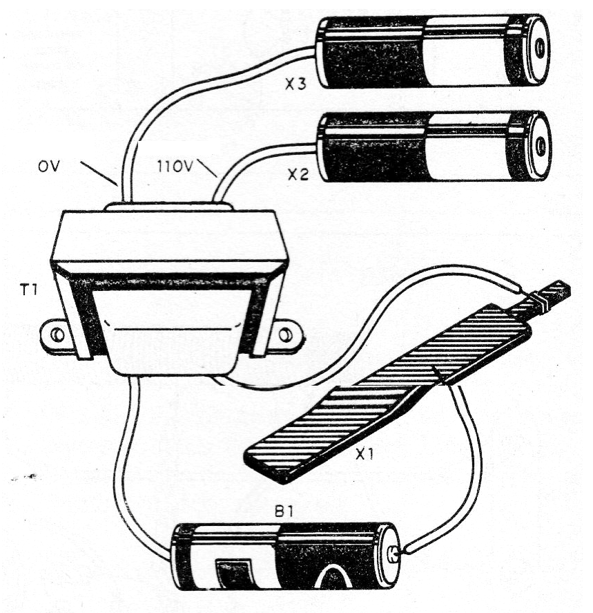
The battery should be medium or large for greater autonomy for the device, since the consumption is high. To use, rub the yarn in the file. Never leave the tip of the cord against the file as the battery will discharge.
By plugging a neon or fluorescent lamp into the circuit outlet, when we rub the wire in the file they will light.
Material list
B1- 1 Medium or Large Stack
X1- Common Flat file
T1- Transformer - see text
X2 and X3 - electrodes - see text
Miscellaneous: box for mounting, wires, solder, etc.


