
This is a simple siren that produces alternating different frequency tones. This is an ideal design for use in alarms or warning systems. The circuit has high power and can be powered by voltages from 9 to 12 V and lower by switching the transistor.
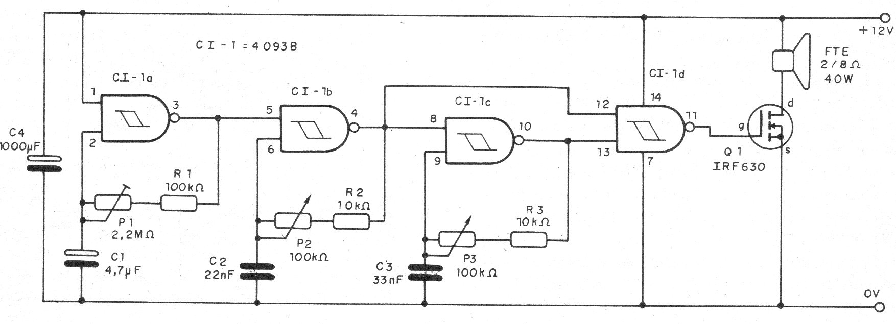
The siren base is three oscillators built around the four ports available on a 4093 integrated circuit.
The first port forms the slow modulation oscillator whose frequency depends on C1 and is set at P1.
The next two ports form two audio oscillators that generate the tones that will be alternated by the first circuit.
The frequencies of these tones are set in the trimpots P2 and P3 depending on the capacitors C2 and C3.
The fourth port of the 4093 is used as a mixer buffers for the tones, applying its output signal to a power MOSFET that has drain charge a good performance speaker.
To power less than 12 V (5 to 9 V), the transistor can be replaced by a BD135 with a 1k resistor in series with the base.
In all cases, the transistor must be provided with an appropriate heat radiator.
In figure 1 we have the complete diagram of the siren.
In figure 2 we have a suggestion of printed circuit board for the assembly.
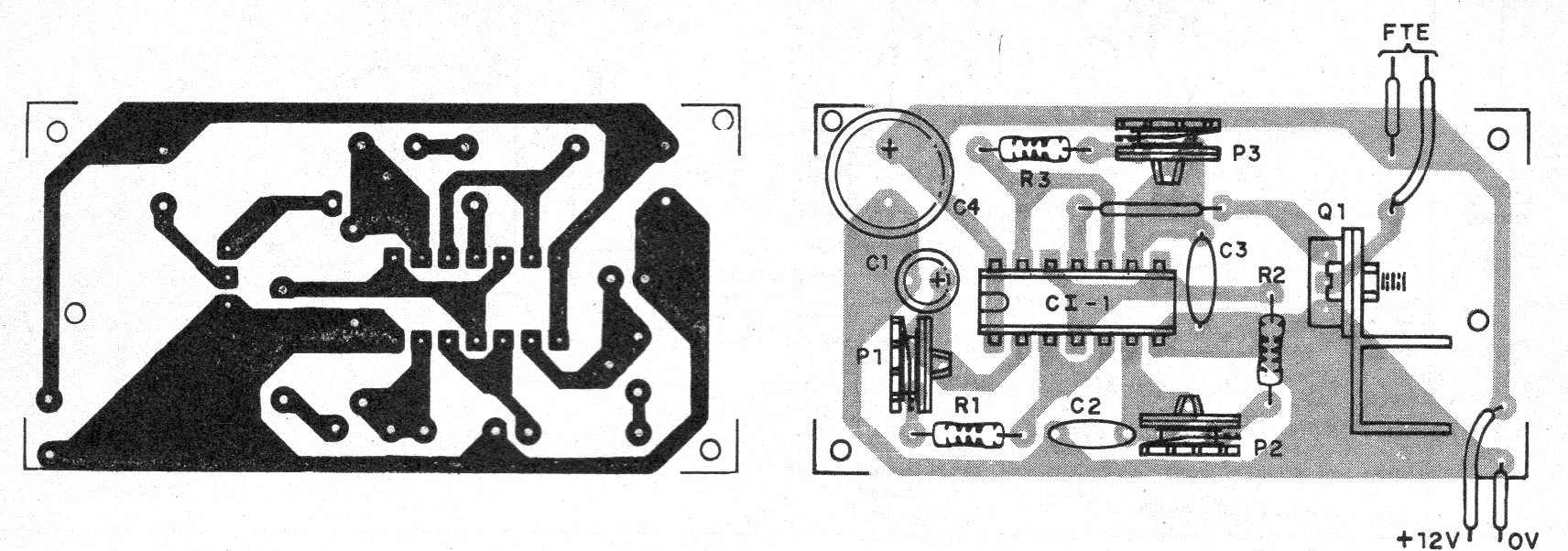
On assembly, note the position of the integrated circuit and transistor, as well as the polarity of the electrolytic capacitors.
The resistors are 1/8 W and for higher performance a heavy speaker should be used.
Material list
CI-1 - 4093 - integrated circuit
Q1 - IRF640 or equivalent - Power MOSFET - see text
P1 - 2M2 ohms - trimpot
P2, P3 - 100 k ohms - trimpots
R1 - 100 k ohms - resistor - brown, black, yellow
R2, R3 - 10 k ohms - resistors - brown, black, orange
C1 - 4.7 uF - electrolytic
C2, C3-22 nF - ceramics or polyester
C4 - 1000 uF - electrolytic
FTE - 2 to 8 ohms - speaker -vertext
Several:
Printed circuit board, mounting box, wires, solder.


