
This circuit in conjunction with communication receivers can be used to aid in the reception of weak signals or to improve the sound quality of old discs. To use it is simple: we must connect the signal source to the input and an amplifier to the output. We then adjust the potentiometers P1 and P2 to obtain the best reproduction, with cut in the noise peaks.
In figure 1 we have the diagram of the apparatus.
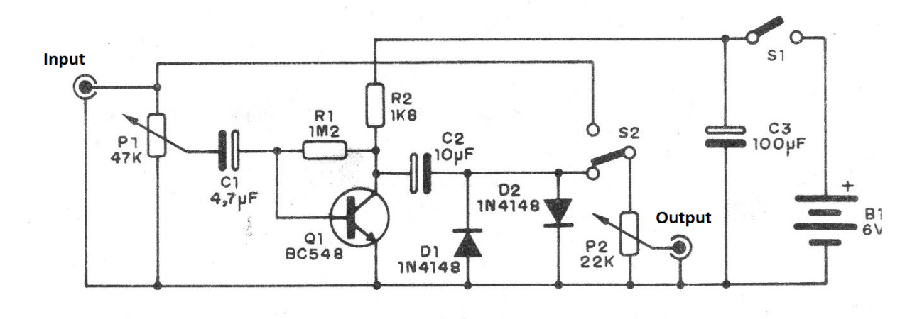
As we can see, the diodes D1 and DZ "clip" the signal, cutting out the unpleasant peaks of noise that occur in radio reception due to static, and in the case of old disks due to cracks or scratches.
The printed circuit board is shown in figure 2.
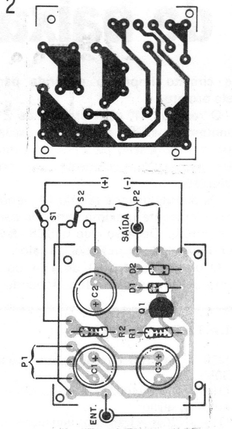
The switch S2 serves to disable the circuit by letting the signal pass directly to the output amp. The input and output cables must be shielded. The resistors are all 1/8 or ¼ W and the electrolytic capacitors for 6 V or more.
The power supply is made up of 4 common batteries and as the power consumption is low, no need to worry about its durability. The resistor R1 can be changed to change the gain of the transistor. Values in the range of 1M to 3M3 can be experienced.
For portable shortwave receivers the signal can be removed from the headphone jack, if any.
MATERIAL LIST
Q1 - BC548 or equivalent - NPN general purpose transistor
D1, D2 - 1N4148 - general purpose diodes
P1 - 47 k - simple linear potentiometer
P2 - 22 k - simple linear potentiometer
S1 – On/Off switch
S2 - 1-pole x 2 positions
B1 - 6 V - 4 small batteries
C1 - 4.7 uF x 6 V - electrolytic capacitor
C2 - 10 uFx 6 V - electrolytic capacitor
C3 - 100 uF x 6 V - electrolytic capacitor
R1 - 1M2 - resistor (brown, red, green)
R2 - 1k8 - resistor (brown, gray, red)
Miscellaneous: printed circuit board, input and output jacks, batteries, solder, mounting box, wires


