
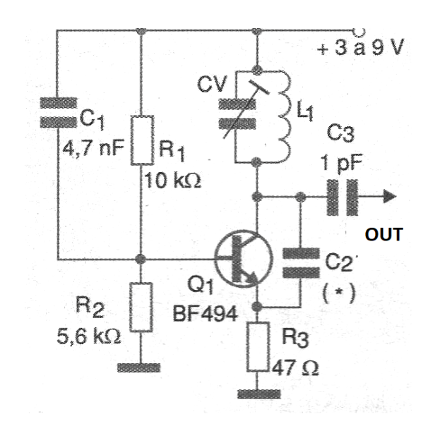
The frequency of the circuit shown in figure 1 only depends on the turns of the coil which will be between 2 and 10 for the indicated range. The wire can be AWG 22 or 24 and the diameter is 1 cm without core. C2 will be from 1 to 4.7 pF for the 70 to 100 MHz band and 10 pF for the 30 MHz to 70 MHz band.
The capacitors must be all ceramic and the trimmer is of the plastic type with a maximum capacitance of up to 20 pF.
The printed circuit board for implementation of this general purpose high frequency oscillator is shown in figure 2.
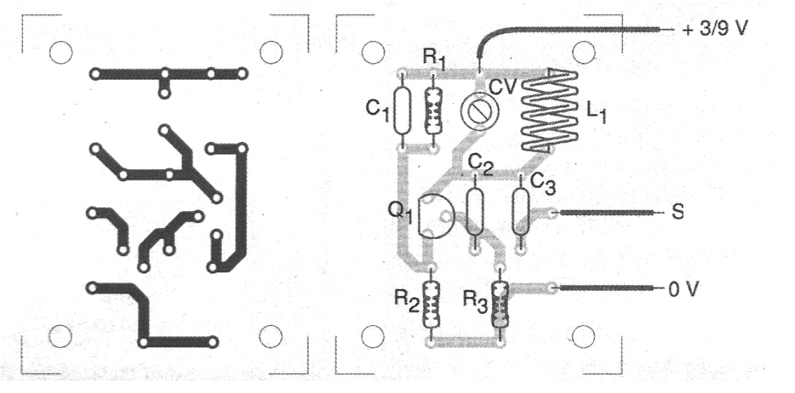
Material list
Q1 - BF494 or equivalent - RF transistor
L1 - Coil - see text
CV - trimmer - see text
R1 - 10 k ohm x 1/8 W - resistor
R2 - 5.6 k ohm x 1/8 W - resistor
R3 - 47 ohm x 1/8 W - resistor
C1 - 4.7 nF - ceramic capacitor
C2 - ceramic capacitor - see text
C3-1 to 4.7 pF - ceramic capacitor
Several:
Printed circuit board, wires, solder, etc.


