
This transmitter operates between 100 kHz and 4 MHz using only one component: a CMOS integrated circuit. Of course, we have the antenna and power supply from 5 V to 12 V as additional elements.
As we can see from the diagram, the inverter ports of a CMOS 4049 integrated circuit are used to form a ring oscillator, where the frequency is determined by two factors: the supply voltage and the transit time of the signal by the integrated circuit. In figure 1 we have the transmitter diagram.
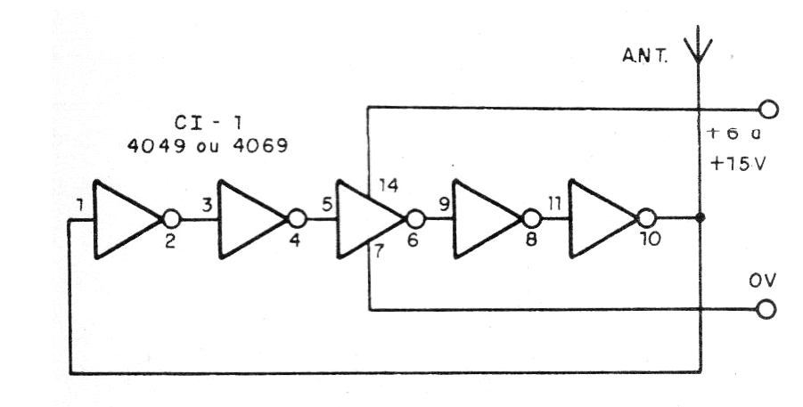
Assembly can be done in a small protoboard. A simple way to vary the frequency is to change the supply voltage. This can be done as shown in figure 2.
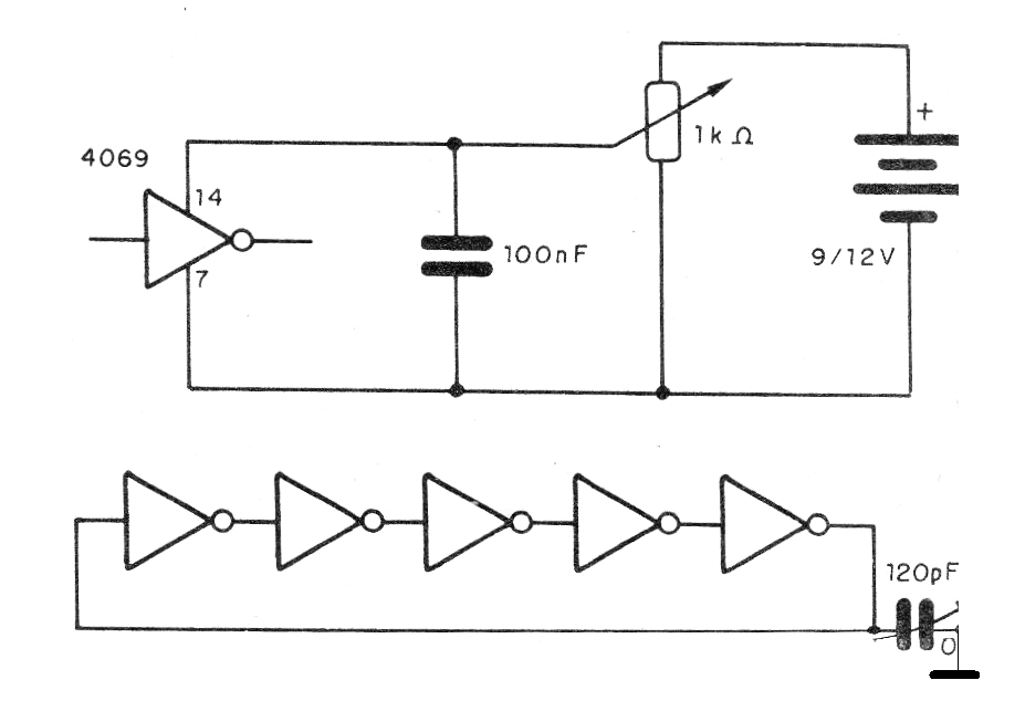
In the first case we have a potentiometer that works as a voltage divider and in the second case a variable capacitor obtained from a transistor radio out of use.
The antenna can be a piece of ordinary wire stretched from 1 to 5 meters. We can use as a receiver a common midrange radio tuned to a free frequency (out of season).
Material list
CI-1 - 4049 - CMOS integrated circuit
Miscellaneous: power supply or batteries, contact array, material to vary frequency (optional), wires, solder, etc.


