
This is a simple didactic assembly that can be performed based on a terminal strip or solderless board. The frequency of the displayed oscillator is controlled by the light incident on an LDR. The circuit can be used as an optical theremin.
Although unijunction transistors are no longer very common components today, many interesting designs can be made with them.
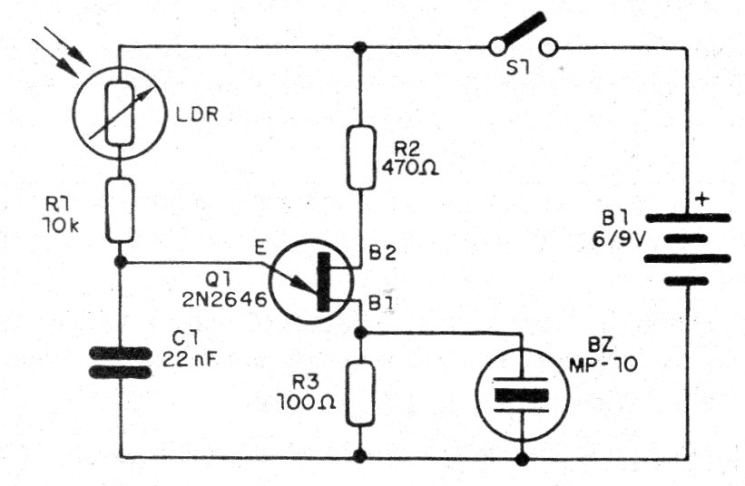
The circuit presented consists of a relaxation oscillator where the frequency depends on both the value of C1 and the resistance presented by the LDR.
As the resistance presented by the LDR depends on the incident light, we have a light-controlled oscillator.
The greater the light intensity, the greater the frequency of the sound produced by a small buzzer.
We can use a small speaker, eliminating R3.
In Figure 1 we have the light-controlled oscillator circuit.
The assembly, based on a strip of insulated terminals is shown in figure 2.
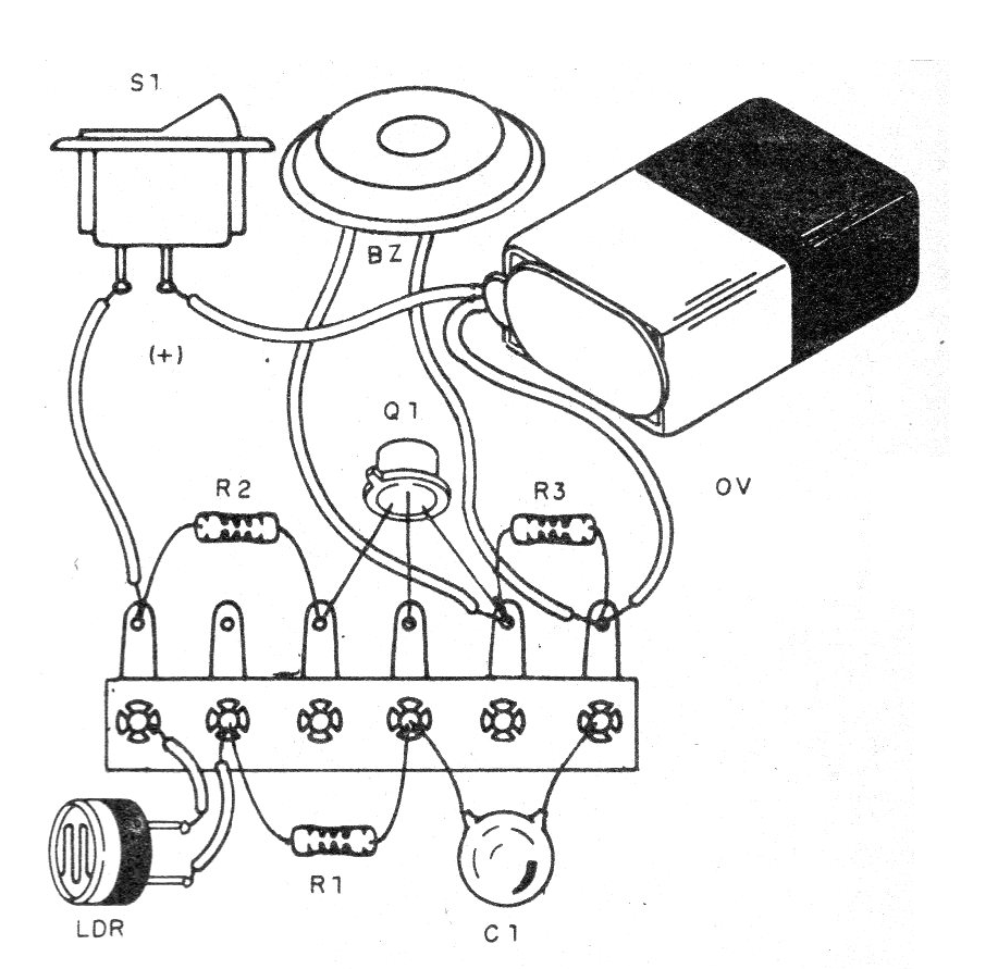
On assembly, note the uni- position transistor position and battery polarity.
Material list
Q1 - 2N2646 - unijunction transistor
LDR - round common LDR
BZ - piezoelectric transducer (capsule)
R1 - 10 k ohms x 1/8 W - resistor - brown, black, orange
R2 - 100 ohms x 1/8 W - resistor - brown, black, brown
C1 - 22 nF - ceramic or polyester capacitor
B1 - 9 V - battery
S1 – On-Off switch
Several:
Terminal strip, battery connector, wires, solder, etc.


