
A bargraph or bar-type indicator with 4 LEDs can be implemented by connecting the four 4093 NAND ports as voltage comparators. The circuit of figure 1 shows how this can be done.
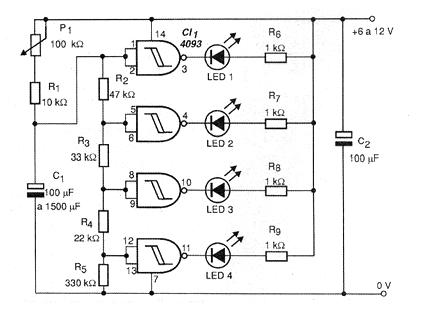
The resistor network from R2 to R5 determines the trigger point of each LED, and the values of these components can be changed according to the application.
The indicators are common red LEDs and the supply voltage of the circuit is made with voltages from 6 to 12 V.
When the circuit is powered, capacitor C1 begins to charge slowly so that the voltage at the input of the bargraph indicator slowly rises, turns the LEDs one by one until the timing is completed.
The setting of P1 and the value of C1 determine the speed at which the timing occurs. Maximum values for P1 are around 100 k ohms and for C1, 1 500 uF which results in a delay of a few minutes.
To start a second delay, wait a few seconds until capacitor C1 is discharged. The value of R5 determines the sensitivity of the circuit and must be changed if the rise does not occur until the end of the scale (four LEDs lit).
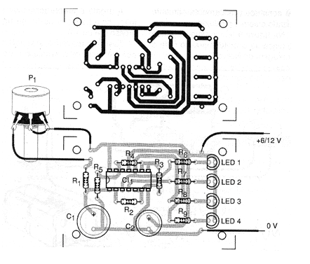
In figure 2 we have a printed circuit board for the assembly of this timer.
Among the possible applications for this circuit we suggest the timing of plays, determination of the time to answer questions in school competitions.
An adaptation that can be made to the circuit is to connect a PNP transistor in the last LED, as shown in figure 3, and trigger a relay with it at the end of the time delay.
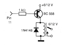
The relay must be 50 mA maximum coil current and voltage according to the one used in the power supply.
A time scale can be aggregated to P1, based on comparisons made with the aid of a common chronometer. The circuit can be powered by common batteries.
Material list
Semiconductors:
CI-1 - 4093 - CMOS integrated circuit
LED1 to LED4 - Common red LEDs
Resistors: (1/8 W, 5%)
R1 - 10 k ohms - brown, black, orange
R2 - 47 k ohms - yellow, violet, orange
R3 - 33 k ohms - orange, orange, orange
R4 - 22 k ohms - red, red, orange
R5 - 330 k ohms - orange, orange, yellow
R6, R7, R8, R9 - 1k ohms - brown, black, red
P1 - 100 k ohms - potentiometer
Capacitors:
C1 - 100 uF at 1500 uF x 12 V - electrolytic
C2 - 100 uF x 16 V - electrolytic
Several:
Printed circuit board, wires, solder, mounting box, battery holder, etc.


