
One way if a high-power load can be controlled by an SCR using a low-power switch such as a sensor, a reed switch, or the contacts of a small relay, is with the circuit shown in figure 1.
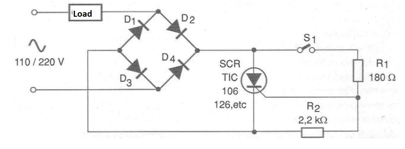
This circuit can control loads of several amps (depends only on the SCR used) with a switch that will not travel for more than a few tens of milliamperes.
For TIC106, for example, this current will be of the order of 0.2 A and for the TIC126 of 20 mA. Of course, the circuit is not isolated from the power grid and the SCR needs to be mounted on a heatsink compatible with the controlled load current.
The diodes must be specified to be able to conduct the current demanded by the load. For currents up to 4 A we suggest the 1N5404 in the 110 V network and 1N5407 in the 220 V network.
In figure 2 we have a suggestion of printed circuit board for implementation of this idea.
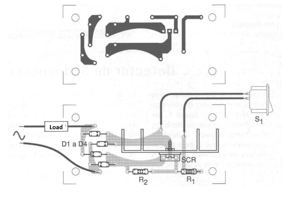
We observed that the tracks leading to more intense currents should be wider. A margin of the order of 1 mm for each amp is recommended.
It will also be interesting to protect the circuit with a fuse in the input. The cables for the S1 switch must be well insulated.
MATERIAL LIST
SCR - TIC106, 126 or any other according to the application
D1 to D4 - 1N5404 (7) - rectifier diodes - see text
S1 – On/Off switch
R1 - 180 ohm x 1 W - resistor
R2 - 2.2 k ohm x 1 W - resistor
Several:
Printed circuit board, heat radiator for SCR, power cable, wires, solder, etc.


