
When one speaks of a relaxation oscillator, one soon thinks of unijunction transistors which, although extremely versatile, are no longer very easy to obtain because of their antiquity. However, what many readers may not know is that it is possible to simulate a unijunction transistor with two bipolar transistors and compile an interesting oscillator for low frequencies.
This oscillator, which can generate signals from 0.001 Hz to 10 kHz typically, has its circuit shown in Figure 1.
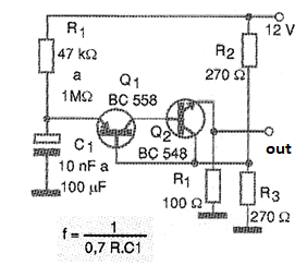
The power supply must be made with voltages of at least 12 V and the frequency is determined by R and C1 according to the approximate formula next to the diagram. This formula is approximated both in terms of the tolerances of the time components and the gains of the transistors used.
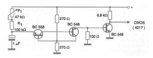
The signal generated by this oscillator can easily trigger CMOS counter inputs if an additional driver transistor is used, as shown in figure 2.
A printed circuit board for mounting the oscillator is given in figure 3 if the reader wishes to implement it independently.
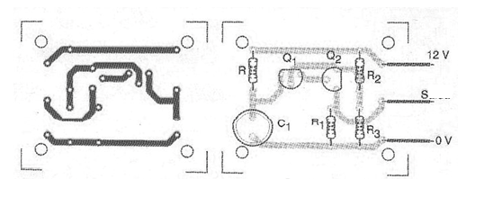
Equivalent transistors can be used and the values of both R and C1 indicated are the recommended limits. R can be replaced by a 47 k ohm resistor in series with a 1 M potentiometer or trimpot to obtain a variable frequency oscillator.
Material list
Q1 - BC558 - PNP general purpose transistor
Q2 - BC548 - general purpose NPN transistor
R - see text - resistor
C1 - see text - capacitor
R1 - 100 ohm x 1/8 W - resistor
R2, R3 - 270 ohm x ½ W - resistors
Several:
Printed circuit board, wires, solder, etc.


