
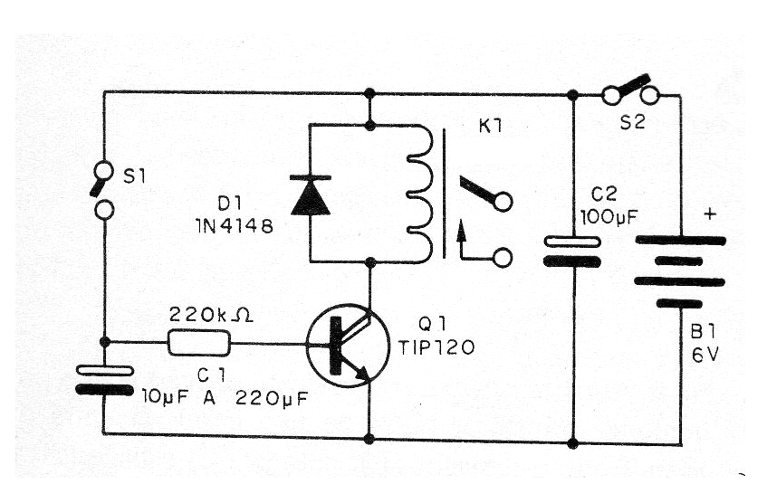
This circuit causes a relay to close its contacts by powering on a load for a certain amount of time and then switching off. We can use this system to connect something with delay, for example, an alarm, to give time to leave the place before it is activated or to feed a lamp of a hallway.
The relay is sized to control loads up to 6 A which results in power ratings up to 600 W in the 110 V network and 1200 W in the 220 V network. The delay can range from a few seconds to more than 1 minute depending only on the value of C1. The system is powered by C1.
In Figure 1, we have the complete diagram of the switch with delay.
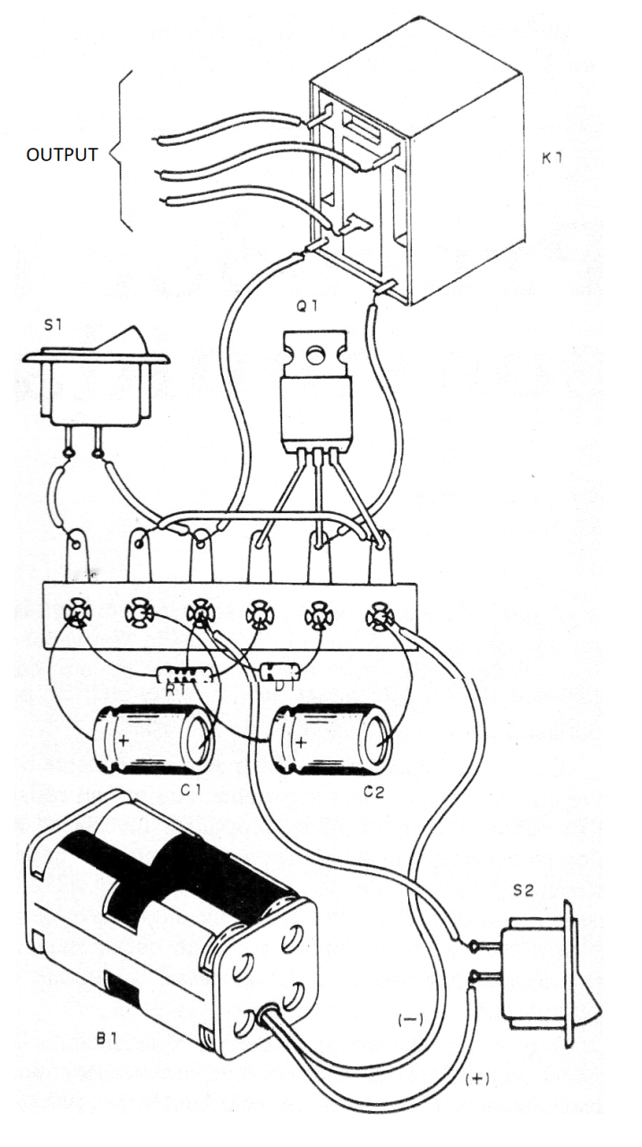
In Figure 2, we have the arrangement of the components at usind a terminal strip.
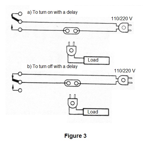
To turn on the load after a certain time use the NC contacts of the relay and to disconnect use the NO contacts. The consumption of the appliance with the relay deactivated is extremely low. The capacitor may have values between 10 uF and up to more than 220 uF, the limit being of the order of 2 200 uF.
Figure 3 shows how to connect the relay to turn the load on or off after a certain time.
Material list
Q1- TIP120 - Darlington NPN Transistor
D1 - 1N4148 - general purpose diode
S1 and S2 - Single switches
B1- 6 V - 4 small batteries
K1 - 6 V Relay
C1- 10 to 220 uF x 6 V or more - electrolytic capacitor
C2 - 100 uF - electrolytic capacitor
R1- 220 k ohms x 1/8 W - resistor - red, red, yellow
Miscellaneous: terminal bridge, battery holder, power cable and outlet for the controlled device, wires, welding, etc.


