
The control we describe can be used with motors from 3 to 12 V and maximum currents of 1 A. The control is of the linear type functioning as a simple rheostat.
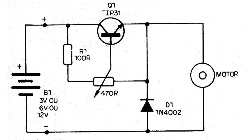
In figure 1 we have the complete diagram of the control.
In figure 2 we have the mounting on a terminal strip.
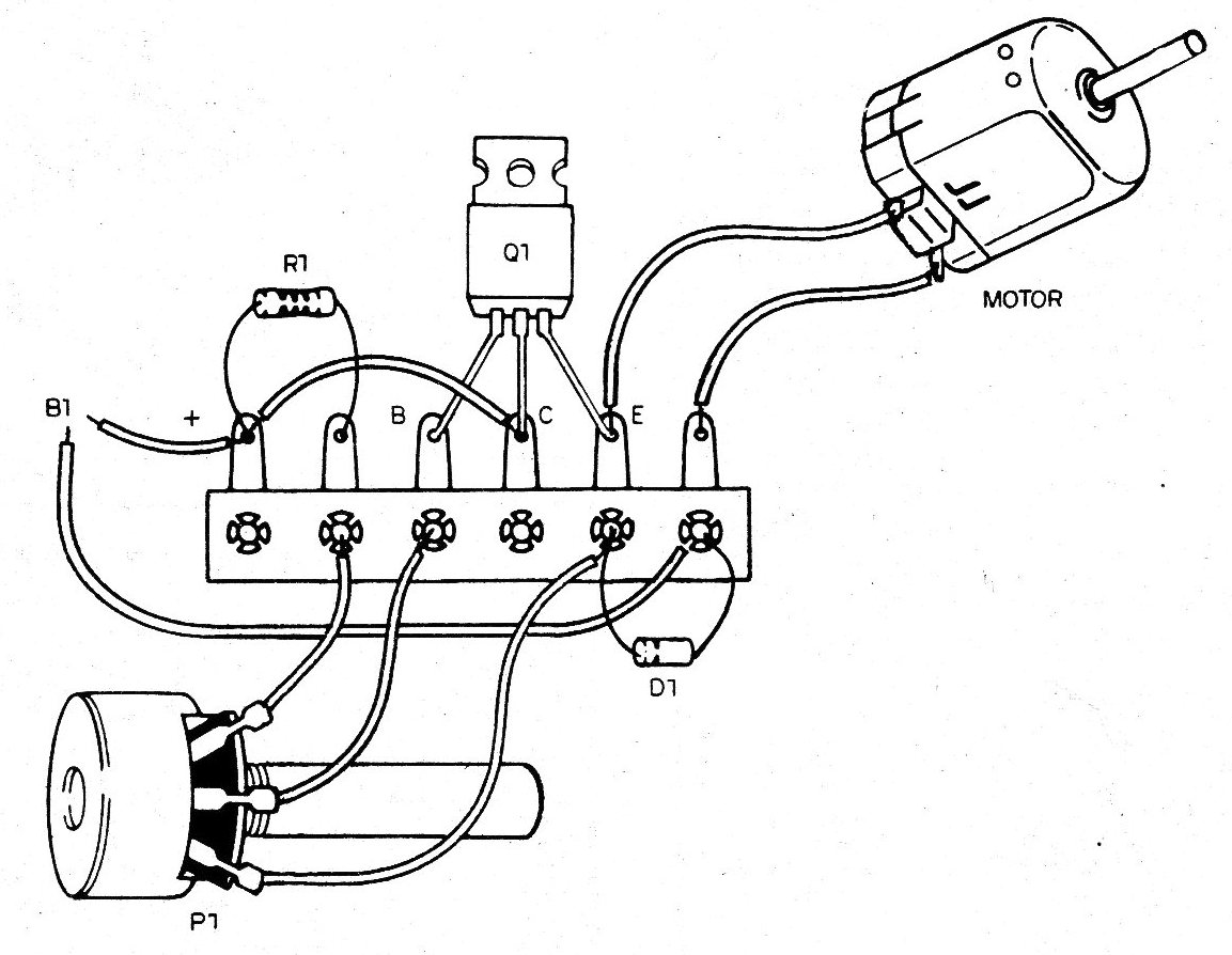
The TIP31 transistor must be mounted on a small heat radiator and its position must be observed.
Diode D1 may be 1N4002 or any equivalent of the same series, including 1N4148.
If you notice pot heating in the motors, increase R1 to 2700 ohms
When connecting the power supply (batteries B1) it is important to observe the polarity, just as in the case of the motor, because if the polarity is inverted it will turn in reverse.
This same circuit can also be used to control the brightness of small lamps (Dimmer).
MATERIAL LIST
Q1 - TIP31 - NPN power transistor
D1 - 1N4002 - silicon diode
P1 - 470 ohms - potentiometer
R1 - 100 ohms x 1/8 W - resistor - brown, black, brown
Miscellaneous: terminal bridge, wires, motor, welding etc.


