
Small power supplies and battery eliminators are always very useful. What we propose to readers is a basic source circuit, which can provide 3.6 or 9 V voltages with currents up to 500 mA, serving to power radios, recorders, walkman, etc.
The circuit has nothing critical, and can be installed in a box for greater ease of use. The only important point is the placement of the supply wires, whose polarity must be observed, especially in the case of the use of jacks and plugs.
Assembly
In Figure 1 we give the basic diagram of the source.
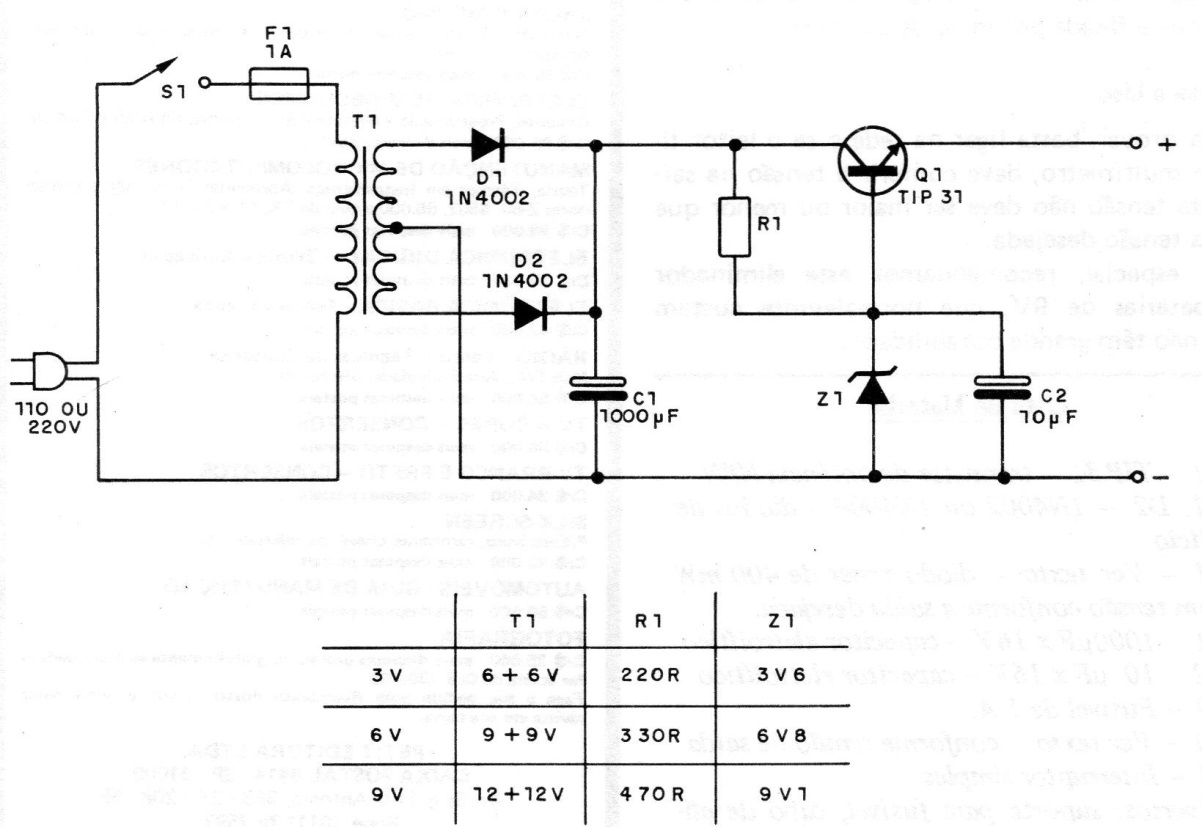
Note that T1, R1, and Z1 have values that depend on the desired voltage at the output. To know the voltage of the device to be powered, just take into account that each cell means 1.5 V.
In figure 2 we have the actual appearance of the assembly.
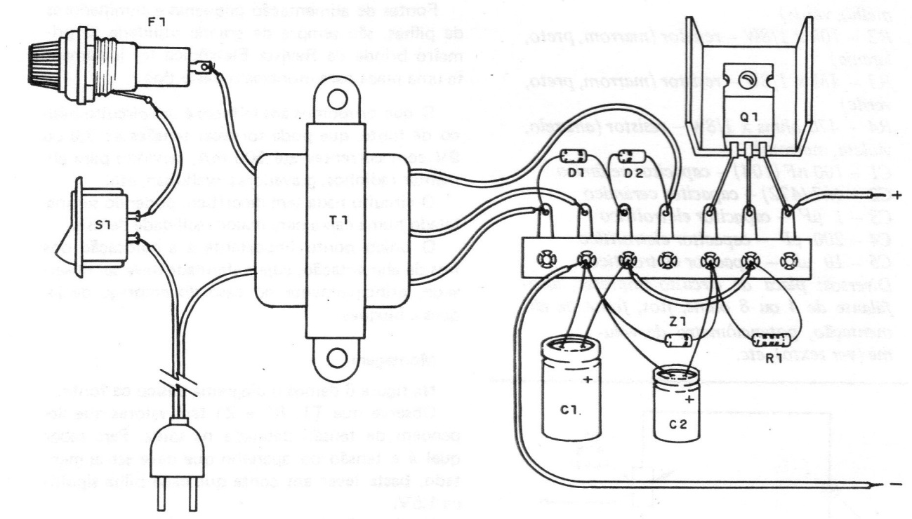
In the assembly Observe the polarity of the diodes D1 and DZ, the zener Z1 and the electrolytic capacitors C1 and C2. The transformer must have primary winding, according to the local and secondary network, according to the desired voltage and current of 500 mA.
The heat radiator of the transistor, consists of a metal plate of approximately 3 x 3 cm, that is fixed by means of screw.
Test and Use
To prove it, simply plug in the network and if the reader has a multimeter, it should check the voltage at the output.
This voltage should not be greater than or less than 10% of the desired voltage. In particular, we recommend this eliminator for 9V batteries, which are usually expensive and do not have great durability.
Material list
Q1 - TIP 31 - NPN power transistor
D1, D2 - 1N4002 or 1N4004 silicon diodes
Z2 - See text - zener diode of 400 mW with voltage according to the desired output.
C1 - 1000 uF x 16 V - electrolytic capacitor
C2 - 10 uF x 16 V - electrolytic capacitor
F1 - 1A fuse.
R1 - See text - according to output voltage
S1 – On-Off switch
Miscellaneous: support for fuse, power cable, mounting box, terminal srrip, wires, solder, etc.


