
This power source can provide adjustable voltages between 0 and 15 V with load currents up to 1 A. This is an ideal source for the assembler, repairer and student workbench. As can be seen from the circuit of figure 1, it is a very simple circuit, zener-regulated, with two transistors in the Darlington configuration at the output.
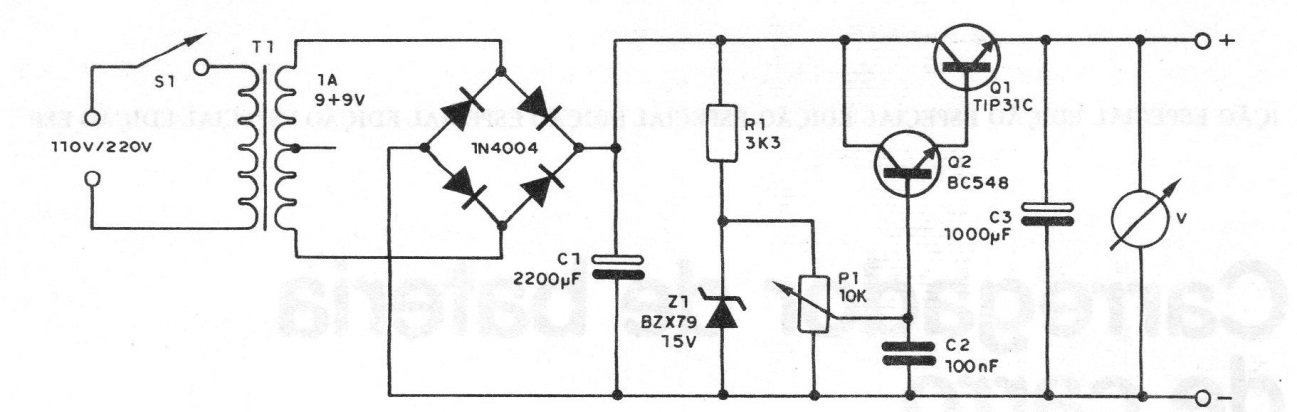
The power transistor Q1 must be mounted on a good heat radiator. This source has no short - circuit protection at the output, so great care must be taken in its use.
The voltmeter, for greater economy, can be of mobile iron, or a connection to the multimeter that will be used to monitor the output voltage. The transformer is 9 + 9 V x 1 A current and its primary winding will have voltage depending on the local grid.
The printed circuit board assembly is shown in figure 2.
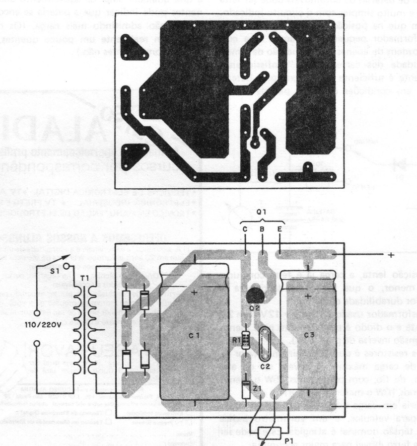
Observe the position of polarized components, such as diodes, capacitors, and zener diode.


