
This simple circuit generates a signal that is picked up by your analog HF television, where horizontal bars are equally spaced. These bars serve to adjust both the antenna system as well as the vertical linearity and height. And a utility circuit for the TV repairman.
Note: This project is from 1987 only for old analog TVs.
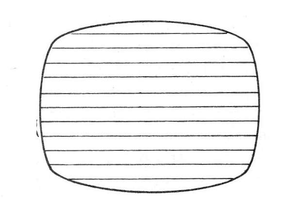
In a perfect image, the spacing of the horizontal bars generated by this apparatus must be uniform. To adjust this spacing there are points on the TV set in your own diagram.
The bar generator we propose is extremely simple serving for non-critical adjustments of linearity and height. As its signal is radiating, we can also use it to check the operation and directivity of an antenna system.
The circuit is powered by 2 or 4 common batteries and has two settings: to separate the bars and the channel in which your signal is to be picked up between 2 and 5.
The range of the signal emitted with a supply voltage of 3 V is of the order of 50 meters and approximately 100 meters with a 6 V supply. Its assembly on a printed circuit board is quite simple.
ASSEMBLY
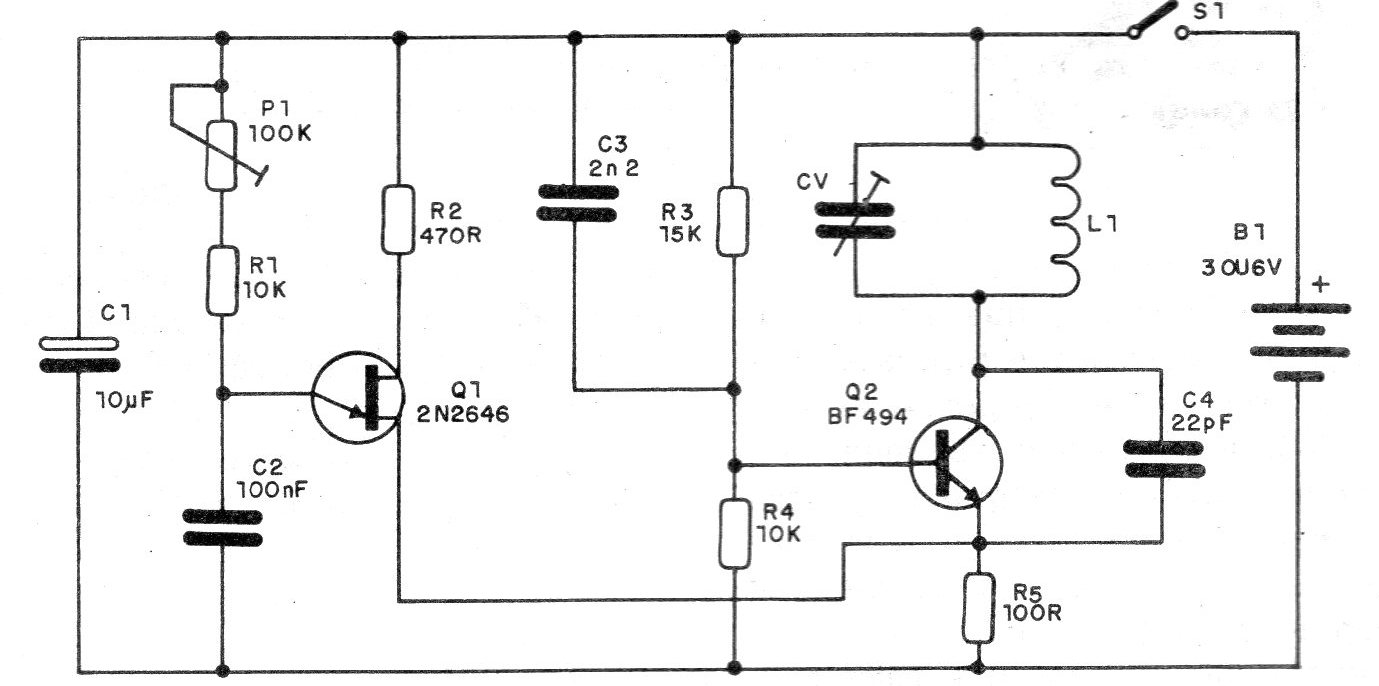
In figure 1 we have the complete diagram of the bar generator.
In figure 2 we have the printed circuit board.
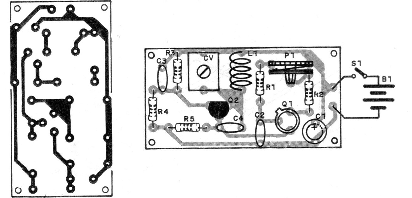
The L1 coil consists of 5 to 6 turns of thick enameled wire (18 to 22), without core, with a diameter of approximately 1 cm. Even ordinary hard wire can even be used. The trimmer is common, plastic or porcelain, with a maximum capacitance of up to 20 pF.
The resistors are 1/8 W or ¼ W and all capacitors are ceramic, except for C1 which is an electrolytic for 6 V or more. Observe the position of the unijunction transistor and also of Q2 in the assembly.
For Q2, BF254 and BF495 are equivalent.
TEST AND USE
Simply place the batteries in the holder and connect the unit near an analog TV tuned to channel 2, 3 or 4. Then CV is set so that the strongest signal from the generator is picked up. In P1 the separation between the tracks is then adjusted, as suggested in figure 3.
The absence of range indicates that the unijunction transistor is not oscillating. To check, connect a speaker in parallel with R5, so there must be sound.
MATERIAL LIST
Q1 - 2N2646 - unijunction transistor
Q2 - BF494 - silicon RF transistor
P1 - 100 k - trimpot
L1 - see text
CV - common trimmer
S1 – On-Off switch
B1 - 3 or 6 V - 2 or 4 small batteries
R1 - 10 k - resistor (brown, black, orange)
R2 - 470 ohm - resistor (yellow, violet, brown)
R3 - 15 k - resistor (brown, green, orange)
R4 - 10 k - resistor (brown, black, orange)
R5 - 100 ohm - resistor (brown, black, brown)
C1 - 100 uF x 6 V - electrolytic capacitor
C2 - 100 nF - ceramic capacitor (104)
C3 - 2n2 - ceramic capacitor (222)
C4 - 22 pF - ceramic capacitor
Miscellaneous: Printed circuit board, two or four cell holder, mounting box, wires, soldering etc.


